State variable filter, looking for advice
Hi guys,
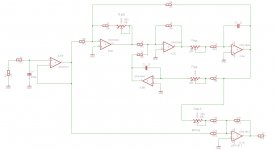
I'm currently working on a design for a notch filter to be used for audio/hifi. It's built from a state variable filter, where the band pass signal is summed with the buffered input signal. The schematic is attached below. I haven't done much theory on filters, so this is drawn using some proven designs as reference, and a prototype is working great. But there is two drawbacks:
1. The output is inverting
Not a huge issue, since i'm cascoding two of these circuits at the moment, but it would be a bit more elegant if I were able to bypass one of the circuits/notches without inverting the phase. Can I just change to a non inverting summing amplifier, without any impact on the filter circuit and its performance? Like this: https://masteringelectronicsdesign.com/wp-content/uploads/2009/08/summing_amplifier_1.png
If so, I could perhaps use the same summing amplifier for a second SVF, instead of cascading two complete circuits to get two notches. Am I right?
2. The frequency pot behaviour is far from linear
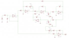
In the prototype, I'm tuning the integrators using a dual gang anti-log pot, but the frequency sweep is very "touchy" making it hard to adjust. After some reading, I've tried to simulate the adjustment range with the pots connected as voltage dividers to ground instead of rheostats. See the alternative schematic.
With a linear pot, I get pretty nice results. I can also reduce the value (and part size) of C2 & C3 from 1 µF to 330 nF, which is a nice bonus. The resistive load seen by the driving OP-amp is 5-6 k, which OPA1644 should handle without any excessive distortion. It's also a lot easier to source a suitable potentiometer. Am I missing something here? Will this hurt noise or distortion performance?
Any advice is greatly appreciated! 🙂
Schematic
Alternative schematic
Hi guys,
I'm currently working on a design for a notch filter to be used for audio/hifi. It's built from a state variable filter, where the band pass signal is summed with the buffered input signal. The schematic is attached below. I haven't done much theory on filters, so this is drawn using some proven designs as reference, and a prototype is working great. But there is two drawbacks:
1. The output is inverting
Not a huge issue, since i'm cascoding two of these circuits at the moment, but it would be a bit more elegant if I were able to bypass one of the circuits/notches without inverting the phase. Can I just change to a non inverting summing amplifier, without any impact on the filter circuit and its performance? Like this: https://masteringelectronicsdesign.com/wp-content/uploads/2009/08/summing_amplifier_1.png
If so, I could perhaps use the same summing amplifier for a second SVF, instead of cascading two complete circuits to get two notches. Am I right?
2. The frequency pot behaviour is far from linear
In the prototype, I'm tuning the integrators using a dual gang anti-log pot, but the frequency sweep is very "touchy" making it hard to adjust. After some reading, I've tried to simulate the adjustment range with the pots connected as voltage dividers to ground instead of rheostats. See the alternative schematic.
With a linear pot, I get pretty nice results. I can also reduce the value (and part size) of C2 & C3 from 1 µF to 330 nF, which is a nice bonus. The resistive load seen by the driving OP-amp is 5-6 k, which OPA1644 should handle without any excessive distortion. It's also a lot easier to source a suitable potentiometer. Am I missing something here? Will this hurt noise or distortion performance?
Any advice is greatly appreciated! 🙂
Schematic
Alternative schematic
Last edited: