.
Very odd problem with this phase splitter/driver in a 300W 6x6550 Ampeg bass amp that has me stumped..............any help appreciated
V1 = ECC83/12AX7
V2 = ECC82/12AU7
V3 = ECC82/12AU7
Cathode follower outputs on the right drive grids of 6 x 6550s in 2 sets of 3 push pull. Each 6550 is biased c 21mA and in practice this means about -70V on V2/V3 cathode outputs.
The amp usually works perfectly. Until, apparently at random and after a few minutes, one half of the output disappears. That is to say one of V2 or V3 cathodes has no signal but normal dc. It can be either one of V2 or V3 output that disappears. Apparently at random. And sometimes both disappear. When this happens there is rustling flicker type sound at the output and of course distortion and a drop of volume.
When the fault occurs all is normal in the phase splitter V1 - normal signal and dc levels on V1 anodes and cathodes.
When the fault occurs, the slightest contact with a scope probe or dc test meter anywhere around the grid circuit of V2/V3 output sections immediately restores normal operation that stays fixed for a few minutes. This makes it impossible to observe there. When the fault occurs no amount of tapping or banging the circuit board will fix the problem - but the slightest electronic contact around V2/V3 output section grids will restore to normal.
I've tried 3 different pairs of ECC82/12AU7 for V2/V3........2 different ECC83/12AX7 for V1. Replaced all interstage coupling caps. Remade all solder joints. All Rs measure well and as far as can tell all dc voltages are correct.
I'm stumped............the oddest thing - thoughts, questions? I don't get how a fault can switch at random between V2 and V3?
I remember reading about grid blocking a long time ago, and I wondered if the -70V heater-cathode potential here is somehow a factor?
Help or pointers appreciated.
When the fault starts, does it slowly or suddenly?. It may be an althered grid resistor or broken. The last case leaves the grid lacking DC returned to cathode taking random bias.
Grid blocking occurs when a large enough signal makes the grid positive respect to cathode and grid current is drawn. This current (large flow of electrons) is stored in the coupling capacitor as a large negative voltage that cuts off plate current. The amp may be oscillating generating this issue, and the oscillo tip is the temporary medicin.
Grid blocking occurs when a large enough signal makes the grid positive respect to cathode and grid current is drawn. This current (large flow of electrons) is stored in the coupling capacitor as a large negative voltage that cuts off plate current. The amp may be oscillating generating this issue, and the oscillo tip is the temporary medicin.
Last edited:
Thanks - when the fault starts it does so suddenly. Thanks for idea about oscillation, shall check it out. It could well be at rf I suppose. At least that seems to fits with random halfs if both are prone and it takes some event to start it......maybe
Shall read up on grid blocking too.
Shall read up on grid blocking too.
The fact that it disappears with touching with a probe points to oscillations.
It can burst into oscillations with warming up.
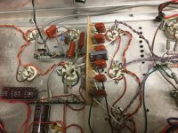
R23/R31 being very high as mentioned by @Icsaszar certainly promotes oscillations.
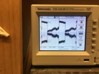
Did you check with a scope? The audio may disappear but there may be a high-frequency oscillation which of course you do not hear and which would not register on a normal multimeter.
Jan
It can burst into oscillations with warming up.
R23/R31 being very high as mentioned by @Icsaszar certainly promotes oscillations.
Did you check with a scope? The audio may disappear but there may be a high-frequency oscillation which of course you do not hear and which would not register on a normal multimeter.
Jan
Thanks for pointers. Yes R23/31 looks unusual and high. And presence of grid stoppers at all suggests some purpose - probably stability against parasitic oscillation. And C7 too in its own way.
Also V2/V3 output section being common anode removes Miller capacitance from the picture and pushes up bandwidth. Think I read ECC82 was originally 2 x EC90 triodes in one package, good for VHF oscillators in the right circuit. So perhaps down to parasitics in the layout?
I need to order some bits and retrieve a faster scope - will report back thanks again.
It seems that you can unplug the feedback loop (J10). If you unplug it, does the problem disappear?
Using large grid stopper resistors is a known stragegy to prevent the amplifier from blocking/choking when it's overdriven, so the 150k resistors are there for a reason. Overdriving is a normal occurrence for guitar amps, and the 150k resistors serve to make it playable. If you lower these resistors, you might get some nice burping/farting distortion when the amp is played hard.
Using large grid stopper resistors is a known stragegy to prevent the amplifier from blocking/choking when it's overdriven, so the 150k resistors are there for a reason. Overdriving is a normal occurrence for guitar amps, and the 150k resistors serve to make it playable. If you lower these resistors, you might get some nice burping/farting distortion when the amp is played hard.
The cathode follower output drives the grids via individual 47k grid stoppers on each 6550 control grid.
I can get the purpose of anti grid-block/grid stoppers resistors on the 6550s. On the ECC82s V2/V3 grids I dont get that - because any grid current from 6550 grids would drive V2/V3 cathodes more positive? That is to make V2/V3 grids more negative. Or have I misunderstood?
I can get the purpose of anti grid-block/grid stoppers resistors on the 6550s. On the ECC82s V2/V3 grids I dont get that - because any grid current from 6550 grids would drive V2/V3 cathodes more positive? That is to make V2/V3 grids more negative. Or have I misunderstood?
The interstage coupling capacitor is the source of farting distortion. It charges up when the previous stage tries to drive the grid of stage that follows it positive, because the driven tube's grid starts to draw grid current which flows through the coupling capacitor. This rectification action increases the voltage across the cap, biasing the stage more negatively and starving it of current. It happens both with single ended stages and with PP stages and in extreme cases it can cause the amplifier to completely drop out after a signal peak and come back after a bout of flatulent sounds. A large grid stopper resistor reduces the grid current that can flow during extreme signal peaks, and thus prevents this from happening.
In your case, there's no coupling capacitor between the cathode followers and the output tubes, so no source of this particular form of distortion. But the cathode follower ECC82s have a capacitor at the input, and can be overdriven by the stage that comes before it. Generally, the stages that are most at risk are the ones that are dealing with the highest signal level and are RC coupled. If you look at the full schematic attached, then you'll see that the 6550s also have rather high grid resistors (47k). That is to protect them against excessive grid current and to give them a slightly softer clipping characteristic. Again desirable traits for a guitar amp.
In your case, there's no coupling capacitor between the cathode followers and the output tubes, so no source of this particular form of distortion. But the cathode follower ECC82s have a capacitor at the input, and can be overdriven by the stage that comes before it. Generally, the stages that are most at risk are the ones that are dealing with the highest signal level and are RC coupled. If you look at the full schematic attached, then you'll see that the 6550s also have rather high grid resistors (47k). That is to protect them against excessive grid current and to give them a slightly softer clipping characteristic. Again desirable traits for a guitar amp.
Attachments
Having read your first post again, I'd suggest shifting your view to the output stage. A pair of 6550s with 600V in the plate and 300V on G2 requires a G1 bias of -32.5 V. This is HiFi bias, for output tube longevity I guess that Ampeg biases them a little colder. But if you need to go much beyond -50V to get at the required bias point, I'd definitely want to check the output tubes. You mentioned a bias of -70V, that's not healthy.
Do you have one or more tubes that show signs of thermal runaway (red plate)? Or does a tube draw grid current? You can check that by measuring DC voltage directly on the tube's pin 5. Normally, for each half of the output stage, G1 voltages should be the same for all three tubes. If one is more than a few tens of millivolts higher than the other, that tube is drawing grid current and should be replaced.
Do you have one or more tubes that show signs of thermal runaway (red plate)? Or does a tube draw grid current? You can check that by measuring DC voltage directly on the tube's pin 5. Normally, for each half of the output stage, G1 voltages should be the same for all three tubes. If one is more than a few tens of millivolts higher than the other, that tube is drawing grid current and should be replaced.
Last edited:

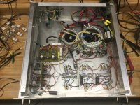
If the k-followers themselves are oscillating it can shift the bias point too. I had to troubleshoot a phantom problem on a similar circuit during initial development. K-followers directly driving 6550’s. I never did observe the actual high frequency oscillation (too high for my scope). It would start up when the audio level got to a certain level, then produce a huge 60-Hz buzz. The oscillation would cut in and out at a 60 Hz rate which became very audible because of the bias shift which happened every time it stopped/started. The LTP stage in front of it was clean, even when this was going on. Only observed at the complementary follower outputs. To fix it I took steps known to help with parasitic oscillations. In the pic you can see the old location of the bias board and the new one. The new one integrated the bias pots, grid stoppers and DC blocks from the prior stage. It minimized capacitance to ground, and the L in the stopper circuit. I twisted each output pair, also reducing capacitance to ground. Also floated the heaters to the bias voltage reference since I had a spare 12.6V winding. The instantaneous h-k voktage was likely the trigger for the local marginal instability. The audio-frequency equivalent circuit was totally unchanged, all this was layout related. The final implementation worked the first time.
It’s probably not exactly the same problem but twenty bucks says it’s something related - a local instability in the k-followers themselves. Oscillations related to what’s sitting in the emitter/source/cathode can be extremely high in frequency - up near the maximum possible for that tube/transistor, making them difficult to observe. Grid stoppers on followers need to be right there, with as small a capacitance/inductance as possible between them and the grid. Especially on followers. And an RF model of the circuit is needed in order to predict.
It’s probably not exactly the same problem but twenty bucks says it’s something related - a local instability in the k-followers themselves. Oscillations related to what’s sitting in the emitter/source/cathode can be extremely high in frequency - up near the maximum possible for that tube/transistor, making them difficult to observe. Grid stoppers on followers need to be right there, with as small a capacitance/inductance as possible between them and the grid. Especially on followers. And an RF model of the circuit is needed in order to predict.
Attachments
I also think this is some kind of oscillation, but I tend to look at component degradation for the cause. This is not a development amp, but one of a type that left the factory by the thousands, presumably in a working state. A power tube that draws grid current can wreak all sorts of havoc, especially because the grid starts acting like a secondary cathode (due to cathode material evaporating and depositing on the grid) and thus creating a completely different load on the cathode follower than would normally be the case. Given the fact that the cathode follower is powered from the same supply as the output tubes' screen grids, a parasitic feedback path for an oscillation is easily formed.
Cathode followers are inherently prone to oscillation. It was devised in a book from Wallman and Valley and in fact there are some kinds of oscillators that use this property, for example the well known between Ham Radio Amateurs Clapp circuit.
Certainly, a parasitic oscillator is easily created around the CF and depending on the PCB layout it can be any flavor of common anode circuit. The high grid resistance on the cathode follower makes that very likely, but unfortunately it is also required to make the amp respond well to being overdriven. But this circuit has worked normally at some point in time, so the problem of oscillation likely comes from a parameter shift of components. The fact that the OP mentions it typically occurs after a couple of minutes indicates to me that the culprit is slowly heating up before it acts up. This behavior is typical for the control grid of a worn out power tube that slowly heats up over time before it starts to emit electrons. Also the fact that the cathode of the CF sits at -70V for the output stage to bias properly is a pointer to something being wrong with at least one of the power tubes. But I guess we have given the OP enough hooks to investigate further, so let's wait for him to return with more info.
I never worked a class AB2 amplifier so I'm of little help here. Also don't know those final tubes.
- Home
- Live Sound
- Instruments and Amps
- Deeply odd phase splitter/driver problem - Ampeg SVT 300