Hi diyaudio world. i need help & guidance.
i want to make a dedicated stereo tweeter amplifier
& active crossovers. As you have guessed; i have very little knowledge about active crossovers, related equation & math.
i want to use tweeters with my sealed woofers
(not sub woofer). i'm currently using lm3886 stereo with those woofers without any active crossover.
The frequency response of my woofers is good upto 2-3Khz approx & that is just my guess because the manufacturer didn't provide much information about those woofers. Actually i don't need high level accuracy, just good music 🙂
For tweeter amps i'll use chipamp like 1875 or maybe tda2050 but i need help to make active crossovers for
tweeters. A good schematic diagram & some advice
enough for me.
as much as i know-
1)Sealed box exhibit a shallow roll-off of about 12dB/octave compared to bass reflex with 24dB/octave roll-off slopes.
2) sensitivity of tweeter & woofer should be same or at least very close.
i have some ne5532 & tl072 op-amps in my hand & i want to use them. i hope I've been able to explain my problem 🙂
Just make sure the tweeter you choose is more efficient than the woofer (this is normally the case),
and a level control in the electronic crossover can match the levels.
Active Filters
and a level control in the electronic crossover can match the levels.
Active Filters
Last edited:
Just make sure the tweeter you choose is more efficient than the woofer (this is normally the case),
and a level control in the electronic crossover can match the levels.
thnks for the input but i need help to make this active crossover. A schematic diagram would be good for me 🙂
Post whatever info you have about the woofer, cabinet, and tweeter, and
some here will offer suggestions for you.
some here will offer suggestions for you.
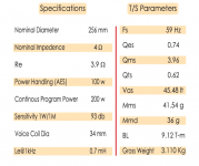
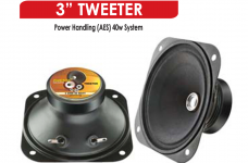
The QTC of my box is near 1. i have no info on tweeters except 40watt power handling & impedance(4ohm), i can post photo only 🙁
Attachments
Last edited:
You can try this circuit. It is set for 100Hz, but you will need to set the frequency to around 2kHz.
Keep all the resistors the same. Divide all the capacitors by 20. Then 68nF/20 ~ 3.3nF each.
Use sockets for the ICs so they can be easily replaced. Add a 10k stereo volume control after the
high pass circuit to reduce the tweeter level. Connect the tweeter in reverse polarity.
https://www.linkwitzlab.com/images/protos/LR2.gif
This circuit assumes a bipolar power supply with +15V/-15V supplies. If you must use a single 30V supply,
the circuit will be somewhat different, with more parts.
The LF alignment of the woofer doesn't affect how the crossover is added.
Last edited:
You can try this circuit. It is set for 100Hz, but you will need to set the frequency to around 2kHz.
Keep all the resistors the same. Divide all the capacitors by 20. Then 68nF/20 = 3.3nF each.
Use sockets for the ICs so they can be easily replaced. Add a 10k stereo volume control after the
high pass circuit to reduce the tweeter level. Connect the tweeter in reverse polarity.
https://www.linkwitzlab.com/images/protos/LR2.gif
This circuit assumes a bipolar power supply with +15V/-15V supplies. If you must use a single 30V supply,
the circuit will be somewhat different, with more parts.
Wow thnks...you're fast!
i'll use two 47k metal films in parallel instead of 23.7 k.
What type of pot? i have 10k linear.
what is the input level for this circuit? Gain, output level?
Do you recommend capacitor for dc blocking?
I'm comfortable with bipolar supply.
The 10k linear pot is fine, if you have either a stereo pot, or two mono pots.
That should be a one-time adjustment to match the woofer and tweeter levels.
This crossover has unity gain, and is for line level use, like at the output of a preamp.
There's no need for DC blocking capacitors, since the amplifiers operate at unity DC gain.
If you have extra op amps, add an input buffer before the filter circuit and it will work better.
The input coupling capacitor shown here is not necessary, and the input resistor value is not critical.
https://www.linkwitzlab.com/images/protos/buffer.gif
Last edited:
The 10k linear pot is fine, if you have either a stereo pot, or two mono pots.
That should be a one-time adjustment to match the woofer and tweeter levels.
This crossover has unity gain, and is intended for line level use, like after the output of a preamp.
There's no need for DC blocking capacitors, since the amplifiers operate at unity DC gain.
why connect the tweeter in reverse polarity?
will you explain please? 🙂
why connect the tweeter in reverse polarity?
will you explain please? 🙂
The tweeter's active filter circuit has -180 degree phase throughout its pass band,
so the tweeter's polarity should be reversed to compensate.
Last edited:
The tweeter's active filter has -180 phase throughout its pass band, so the tweeter's polarity
should be reversed to compensate.
It's very difficult for me to understand 😀
i thnk u again. i'll be back soon.
For high frequencies, C approaches a short. Thus the treble section becomes an inverting amplifier, with its noninverting input ~shorted to ground.
You still have to adapt the R and C values according to the desired crossover frequency and impedances - I very much doubt that you'll want to cross over at 99 Hz as shown, right?
Your tweeter's 40 W system power spec is for a given crossover frequency and order. The driver itself probably won't handle more than 1-5 W.
It's unfortunate that you have zero specs on this, which makes it hard to choose a good crossover frequency. The slightly smaller Visaton TW6NG (a 6 cm / 2.5" job) is good for about 2-3 kHz up. You probably don't want to run most 10" woofers beyond 1.5 or 2 kHz. Finding enough overlap may prove a bit difficult. Not to mention that directivity is likely to be problematic. (Ideally, the tweeter would have to be placed in a waveguide roughly the woofer's size. No, you probably can't buy one off the shelf.)
Normally you would make a 3-way with these, with an additional midrange driver. Not that I like a lot of typical dedicated midranges, they have to be crossed over higher than I'd like (which is ~300 Hz ideally).
A plain L-R crossover also won't take care of any other EQ that the drivers may require yet (and they probably do). Time alignment may have to be done via baffle design, otherwise perhaps an allpass would help.
You also want to have something the at least vaguely resembles a measurement microphone for a project like this, and ARTA or at least REW.
BTW, matching driver sensitivity is not required at all for active loudspeakers - after all adding some gain or attenuation and choosing bigger or smaller power amps is quite easy.
I haven't even touched on a typical active speaker problem yet, audible hiss.
Essentially, an active speaker has all the complications of a passive one, plus those of a crosssover and power amplifier.
You still have to adapt the R and C values according to the desired crossover frequency
and impedances - I very much doubt that you'll want to cross over at 99 Hz as shown, right?
See post #6.
you mean low pass section??For high frequencies, C approaches a short. Thus the treble section becomes an inverting amplifier, with its noninverting input ~shorted to ground.
Attachments

Ok, i'll add a volume control pot before the buffer op-amp.The 10k linear pot is fine, if you have either a stereo pot, or two mono pots.
That should be a one-time adjustment to match the woofer and tweeter levels.
if i want to use lowpass section for my woofers what changes need to be made in the low pass circuit?You can try this circuit. It is set for 100Hz, but you will need to set the frequency to around 2kHz.
Keep all the resistors the same. Divide all the capacitors by 20. Then 68nF/20 ~ 3.3nF each.
Use sockets for the ICs so they can be easily replaced. Add a 10k stereo volume control after the
high pass circuit to reduce the tweeter level. Connect the tweeter in reverse polarity.
The cutoff frequency is very high, 100hz as you know 🙄
What do you recommend; input buffer without gain or output buffer with gain? Rod elliot suggest both, but i don't want to use three stereo opamp here 🙁
Attachments
Last edited:
if i want to use lowpass section for my woofers what changes need to be made in the low pass circuit?
The cutoff frequency is very high, 100hz as you know(
The low pass circuit does not affect the deep bass. It is for the 2kHz crossover point.
As said before, use 3.3nF capacitor and same resistors.
The low pass circuit does not affect the deep bass. It is for the 2kHz crossover point.
As said before, use 3.3nF capacitor and same resistors.
Oh, ok then 3.3nf for both circuits 🙂
anything you want to say about buffers?
(plz see my earlier post).
Can i change the input buffer to non-inverting amplifier with 6dB of gain if i face gain related problem?
The source would be mp3 player, this is why i'm asking?
Sorry for so many questions.
Can i change the input buffer to non-inverting amplifier with 6dB of gain if i face gain related problem?
You can have as much gain in the buffer as you want.
If you have enough gain now, adding the filter will not change that, since it has unity gain.
Last edited:
- Home
- Source & Line
- Analog Line Level
- Dedicated tweeter amp & crossover