First lessons.
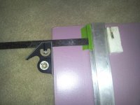
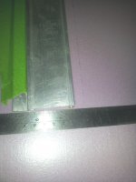
This is a different animal. I used blade holder I described earlier. The first cut produced a lot of ripping and separated the membrane on the bottom side. The regular paper FC has a much more secure bonding.
I lowered the angle of the blade and did a 3/4 depth cut and then gently let the blade follow the first cut all the way through. Perfecto!!!
For curiosity I did a couple cuts on a table saw but it grabs and flies too easily to be safe. My saw is outside and any little wind grabs it. Still hope to use some mechanical tool for the angles.
Attachments

Bob,
Nice work! You are fast. The only thing to adjust is to move the piece that separates the top of the driver chamber and back wall of driver chamber inwards to preserve the horn channel gap at the expense of making the driver chamber volume a tiny bit smaller. After that where possible adjust the pieces (or as you say, " arrange whatever pieces come your way. " 🙂 ) to achieve the same horn channel gap, always at the expense of the volume or external dimensions. So if you have not cut the two large sides you may want to make them a tad larger. But 0.593 in and 0.50 in are very close.
Nice work! You are fast. The only thing to adjust is to move the piece that separates the top of the driver chamber and back wall of driver chamber inwards to preserve the horn channel gap at the expense of making the driver chamber volume a tiny bit smaller. After that where possible adjust the pieces (or as you say, " arrange whatever pieces come your way. " 🙂 ) to achieve the same horn channel gap, always at the expense of the volume or external dimensions. So if you have not cut the two large sides you may want to make them a tad larger. But 0.593 in and 0.50 in are very close.
Bob,
Nice work! You are fast. .......
"Haste makes waste" as they say. I think I have to cut new side panels and trim anyway. I read the drawing wrong if I want to put everything together and close it up with the last side. I was shooting for an 8" outside width but reversed the overlap. (done that too many times and should know better 😱) What do you consider the optimal internal side to side dimension ? Not a problem as the old sides can be used for some of the inner plates.
PS-Might be helpful to add an angle or front view to your drawing.
7 inch internal width. If the clear plastic cover comes off too easily you may want to peel back to bare foam before gluing or else it will eventually delaminate.
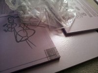
I lied, The carbide blade on the table saw made quick work of the trimming. Got two 7" deep boxes (scotch tape). Need to clarify the XXXXX is back and not an error correction. Just a bit confusing. Final internal is 12x7x27, correct?
Finished for the night - back in the morning.
Finished for the night - back in the morning.
Attachments
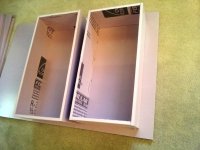
Xxxxx is cross-out because the perspective drawing from which this based had a wall in the third dimension out of page. Ignore part that is crossed out. The boards look thicker than I imagined. Interesting that the carbide blade can trim. Is it a pain to cut with box cutter or table saw was good for ensuring a consistent thickness board? Nice work. You should be done soon at this rate. What will you use to glue?
O.K. I can see the mouth but I'll probably cut it out after I know the box is square. The saw did a great job as the pieces were small enough to control with two hands. If someone wants to use that, I'd suggest blade cutting with some excess - using as many factory edges as possible, then trimming to size.
Same as the last time. Hot glue for assembly and Gorilla Glue (Clear this time) for the last panel. I plan to get everything in place with tape first so progress will slow significantly. It's hard to believe after all my "flippin & spinnin" today I just got two boxes, but oh well.😉
Same as the last time. Hot glue for assembly and Gorilla Glue (Clear this time) for the last panel. I plan to get everything in place with tape first so progress will slow significantly. It's hard to believe after all my "flippin & spinnin" today I just got two boxes, but oh well.😉
xrk971,
The throat hole in the top of the compression chamber is 1" radius. The plans are originally drawn for 1/2" material.
The throat hole in the top of the compression chamber is 1" radius. The plans are originally drawn for 1/2" material.
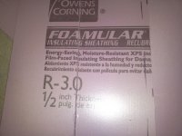
The insulation says .5 inch and R3.0. Hmmm, that tells me one of those is wrong. Type IV polystyrene is R5.0 per inch.
Nice work Bob.
Nice work Bob.
Thanks,
I did a few conversions for ease of layout as I don't own a 10th inch ruler. 🙂
The cover film is garbage so I stripped it completely on the inside face of both sides. Getting ready to start layout, keying on all inside throat dimensions.
I'm changing to Gorilla Glue for the shell construction (after internals layout) thinking it will eliminate having to run a sealing bead of hot glue on that joint.
Attachments

Last edited:
Bob,
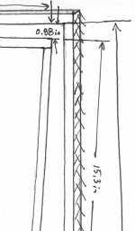
Nice job on cleaning up the drawing. I may have a typo on one of the throat dimensions where it says 2.80 in, I think that should be 3.48 in as it should be bigger than the number before it. The best thing to do is to print a full scale drawing and measure how big the foam should be, or use calipers to measure the drawing and multiply by scale to get the actual size for the pieces that need to be cut. The important dimension is that the sharp edge for the piece that hooks up should be located 8.0 in from the back edge where the mouth of the horn is. The bottom of that piece where the expansion of the final mouth is should be located 4.56 in in from the back of the speaker and 5.80 in above the bottom of the bottom wall of the mouth.
Nice job on cleaning up the drawing. I may have a typo on one of the throat dimensions where it says 2.80 in, I think that should be 3.48 in as it should be bigger than the number before it. The best thing to do is to print a full scale drawing and measure how big the foam should be, or use calipers to measure the drawing and multiply by scale to get the actual size for the pieces that need to be cut. The important dimension is that the sharp edge for the piece that hooks up should be located 8.0 in from the back edge where the mouth of the horn is. The bottom of that piece where the expansion of the final mouth is should be located 4.56 in in from the back of the speaker and 5.80 in above the bottom of the bottom wall of the mouth.

Bob,
Good catch, a horn should continue to expand so make the 0.5 pinch point the same as 0.88 inch. I did that in my model when I took calipers to measure it.
Good catch, a horn should continue to expand so make the 0.5 pinch point the same as 0.88 inch. I did that in my model when I took calipers to measure it.
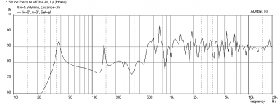
Kenlbird asked me if the Audience A3 driver can work in the DNA. I ran a simulation in AkAbak which confirmed my suspicion that you can't just stick any driver in this cabinet. The A3 is really not going to work at all - Sorry Ken.
I tried reducing the driver chamber volume all the way down to 1.5 liters and making the throat from the driver chamber go from 0.7 in to 0.4 in slot to get terribly bass-peaked response that still doesn't look good. Results are attached below. First is just sticking the A3 into the DNA cabinet as designed, and the second is reducing the chamber to 1.5 liters and reducing throat to 0.4 in.
I tried reducing the driver chamber volume all the way down to 1.5 liters and making the throat from the driver chamber go from 0.7 in to 0.4 in slot to get terribly bass-peaked response that still doesn't look good. Results are attached below. First is just sticking the A3 into the DNA cabinet as designed, and the second is reducing the chamber to 1.5 liters and reducing throat to 0.4 in.
Attachments

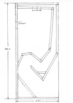
Updated Plan for DNA-inspired horn (correct aspect ratio)
Bob pointed out a big problem with the drawing/plan I posted earlier: the aspect ratio in vertical and horizontal did not make sense. It was my mistake for doing a perspective correction in the horizontal direction to flatten the 3d drawing, but I did not apply any correction to the vertical dimension. Hence the drawing was distorted and too tall (by some odd 20%). As you can imagine, this caused all sorts of problems as Bob was cutting foam and trying to fit it all in place. My apologies for messing this up.
Anyhow, I re-scaled the drawing so that the horizontal and vertical aspect ratio is now correct. All I can say is that the drawing now shows a box that is 28 in tall and 12.5 in deep (externally). The width (into page) is still 7 in internally.
We have since also learned new info that the hole leading from the driver chamber to the horn path is 2.0 in diameter. The equivalent slot throat width is actually 0.45 in for a 7 in wide chamber. The simulation is not very sensitive to this dimension within reason. It controls the upper frequency cutoff - so if you want less HF leaking out of horn, use smaller dimension, at the expense of bass SPL level (less efficient). Any value between 0.45 and 0.70 in wide slot should work. And if you use a hole, 2.0 in dia to 2.5 in dia, should work.
I will leave it up to the interested builder to use dial calipers to come up with his own measurements based on the drawing. I have it provided as a png and pdf file.
Attachments
.......... It controls the upper frequency cutoff - so if you want less HF leaking out of horn, use smaller dimension, at the expense of bass SPL level (less efficient). Any value between 0.45 and 0.70 in wide slot should work. And if you use a hole, 2.0 in dia to 2.5 in dia, should work.
.........
Not a problem. Sometimes it's D-D-DIY 🙂
How much will changing the throat effect the extension - if at all ?
Does your simulation show an optimum mouth area? If might be helpful to work backwards from that. - actually from both ends and meet in the middle.
Last edited:
I just checked the simulation, the 0.45 in wide throat slot vs the 0.70 in slot has the same bass extension and same SPL level at 34 Hz (peak). The main difference was less HF leaking out around 700 Hz. Probably fine to go with smaller 0.45 in wide slot or 2.0 in dia round hole for throat.
- Home
- Loudspeakers
- Full Range
- Decware DNA Horn