Hi. Sorry if this is a ''Nob question''. I am trying to upgrade my current V/C on pre amp to Audio Academy Muses V/C with remote.
On the installation it calls for a 47 to 100uF DC blocking cap to be used at the input. then added to these caps need a Bi-passing cap ''10nF to 100nF film or C0G (NP0) ceramic''
''Use direct input connection only when it is assured that no DC voltage will be applied to the inputs. Use direct output connection only when no DC voltage will be applied to the inputs AND outputs of the chip. In all other cases high quality DC blocking capacitors shall be used. High quality polypropylene capacitors present the best choice for the output DC blocking when the control is feeding high impedance loads. They get pricey at higher than 10uF values. High quality non-polar electrolytic capacitors of 47uf to 100uF provide good results when bypassed with 10nF to 100nF film or C0G (NP0) ceramic capacitors.''
How do you do that,
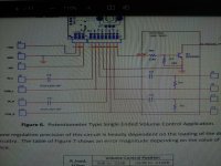
Have attached the wiring diagram shown on the web site
Cheers for any help
On the installation it calls for a 47 to 100uF DC blocking cap to be used at the input. then added to these caps need a Bi-passing cap ''10nF to 100nF film or C0G (NP0) ceramic''
''Use direct input connection only when it is assured that no DC voltage will be applied to the inputs. Use direct output connection only when no DC voltage will be applied to the inputs AND outputs of the chip. In all other cases high quality DC blocking capacitors shall be used. High quality polypropylene capacitors present the best choice for the output DC blocking when the control is feeding high impedance loads. They get pricey at higher than 10uF values. High quality non-polar electrolytic capacitors of 47uf to 100uF provide good results when bypassed with 10nF to 100nF film or C0G (NP0) ceramic capacitors.''
How do you do that,
- does the bi-pass capacitor bridge over the blocking capacitor,
- or does it does it go from the blocking capacitors output to ground?
Have attached the wiring diagram shown on the web site
Cheers for any help
Attachments
And it basically does nothing. Go read Cordell and Self. It is a "must be good" DIY hack, not engineering.
That's not entirely true.And it basically does nothing.
The inductance associated with the package and leads of one cap will resonate with the associated inductances and capacitance of the other cap and actually make the impedance rise at that resonant frequency. (And vice versa - usually you get two peaks) You can measure this or simulate it easily with an RF simulator or Spice variant.
That's not nothing, but I don't really think that is what anybody wants. It sure could affect the sound, though.