I have a spdif splitter circuit based on 7404 that is not working.
There are 2 stages to this.
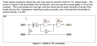
1 input spdif to convert to TTL
2.The TTL output from stage 1 goes to 2 TTL to spdif converters, each using two inverters.
For circuit diagram for each stage, see here https://sound-au.com/project85.htm
When I connect a signal generator with a few MHz square wave, I can see on my Tektronix 'scope the output following the input so potentially all good.
When I connect the digital output (spdif) from a streamer and either output to a DAC, the audio is distorted and sometimes stops altogether.
I need to retest but I think the same happened when I used a CD player digital output. To debugI tried to view the spdif signal to the circuit but because it is non repetiive, the scope would not trigger so I could not see the input and output traces clearly.
Maybe I'm using the scope incorrectly?
I do have a digital scope that I think may have storage facility. (shows how ofter I've used that LOL) .. if I can figure out how to use that.
In the meantime any suggestions welcome.
There are 2 stages to this.
1 input spdif to convert to TTL
2.The TTL output from stage 1 goes to 2 TTL to spdif converters, each using two inverters.
For circuit diagram for each stage, see here https://sound-au.com/project85.htm
When I connect a signal generator with a few MHz square wave, I can see on my Tektronix 'scope the output following the input so potentially all good.
When I connect the digital output (spdif) from a streamer and either output to a DAC, the audio is distorted and sometimes stops altogether.
I need to retest but I think the same happened when I used a CD player digital output. To debugI tried to view the spdif signal to the circuit but because it is non repetiive, the scope would not trigger so I could not see the input and output traces clearly.
Maybe I'm using the scope incorrectly?
I do have a digital scope that I think may have storage facility. (shows how ofter I've used that LOL) .. if I can figure out how to use that.
In the meantime any suggestions welcome.
If this is the circuit you've prototyped, it's important to use the 74HC04 inverter and not "7404" as you mention in post #1. HC is faster, higher bandwidth, and crucially, has much much higher input impedance. So the feedback network R2-R3 doesn't fight with the inverter's Zin.
Things to possibly check:
Things to possibly check:
1. Is your inverter in fact a 74HC04 ? (If you happen to own a 74AC04, even better!)
2. Adjust your signal generator to give a square wave whose amplitude is just a smidgen less than the 0.2V spec minimum. Does your gear work well in these conditions?
3. Increase C1 by a factor of ten (10nF ---> 100nF) to deal with the slowest bitrate SPDIF allows. Does your gear work well in these conditions?
Attachments
Yeah, it's 74HC04...apologies i was being lazy.
Originally I did put 0.1uf ceramic instead of the 10 nf as I had some spare but it did seem worse.
I did notice that the signal generator output dropped when connected to the circuit: 100ohm load...so I'm wondering if I have used 10ohm instead, I usually check resistor values on DVM, the resistors were part of a kit labelled by the seller so could be a source of error.
Thanks for reply, some thing to try out tomorrow.
BTW In the past I have fitted the TTL to spdif circuit to 2 cd players in order to have both optical and electrical digital out so I know that works, although I did use 3 74HC04 in parallel.
I took your advice in keeping it simple by using signal generator instead of jumping to using spdif.
Reading the data sheet it recommends a bypass capacitor. This got me thinking.
The circuit is power by usb with a long lead, maybe 1m and I see to recall it worked better when connected to my DIY 5v supply, power leads about 15cm.
Touching a 0.1uf capacitor across the pcb power cleaned up the ground and the both input and output signals were correct.
It is now working after fitting 47uf bipolar (reuse of removed part) so onwards to doing side by side DAC mods comparison.