Hi folks!
I need a low power standby transformer that can produce 12V DC after rectification. It should preferably have a low no-load consumption (P0<0.4W). While searching for such transformers, I realised that the no-load output voltage is significantly higher. This means that when the circuit is in no-load condition, the filter capacitors will charge up to no-load voltage, which is not good. What is the general practice with standby transformers? How can I prevent too much voltage rise without losing the benefit of a standby transformer?
See page 12 of the datasheet for more details. I am looking for part number BV EI 303 8008.
https://www.tme.eu/Document/412ff82a0d9ae839d6b24853d8f56596/Hahn-E.pdf
Thanks in advance
Adam
For this very reason most use a 35V filter cap followed by an 7812 and a series resistor + power on or standby LED to have at least some current. Solved.
If you have a good reason not to use a regulator you can use a 9V transformer and a 16V filter cap.
If you have a good reason not to use a regulator you can use a 9V transformer and a 16V filter cap.
Last edited:
Small transformers such as intended standby use always have poor regulation meaning the no/low load voltage is high. It could be as high as 20 to 40% It is a consequence of them having small cores and poor efficiency. You just have to design around that aspect of them.

depends on your required power when needed. most ac/dc encapsulated power supplies up to 20W have a noload power < 0.4W.
these designs are a consequence of EU noload power regulations.
at tme.eu less than 15 euro. cez20.0-230/12V , 20W
these designs are a consequence of EU noload power regulations.
at tme.eu less than 15 euro. cez20.0-230/12V , 20W
Or just use a real power switch and have the benefit that stuff is truly deenergized. Zero risk is a nice feeling.
What is the general practice with standby transformers? How can I prevent too much voltage rise without losing the benefit of a standby transformer?
I don't know whether it's general practice or not, but my practice is to accept the reality that, occasionally, the power company sets my AC mains at (normal voltage + 10%); and also, the standby transformer's no-load output can be 1.5X its yes-load output. I treat these as additional design constraints, requirements which my design must satisfy without exception.
I've only uploaded one project (schematics, PCB Gerbers, measured data, et al) to these diyAudio Forums, which includes a standby DC subsystem. After studying the problem and preparing several candidate solutions, the option I eventually chose for my design, was the one mentioned by @basreflex in post #4 above: I used a 2 Watt encapsulated AC-to-DC converter from MeanWell.
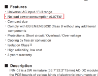
Since you appear to need 9V-AC (12V-DC ?) at 2 watts, I suggest you consider Mouser part number 709-IRM02-12 (USD 5.10 in thru-hole, USD 5.60 in surface mount). Its output is 12VDC at 167mA. Specs below. Carefully note its PCB area and chassis volume; the MeanWell is quite a bit smaller than a complete transformer-based DC standby approach.
_
Attachments
Agree with Mark/reflex. The little switcher blocks are pretty amazing. Very high efficiency (80+%) and very low no load consumption. Smaller too. I've used them in numerous projects some over 10 years old now that sit in non-temp controlled spaces like attics and outdoors in an enclosure. No failures yet. I just make sure they are kept dry. Another bonus of the many of the switchers is they run from 90-277VAC so power 120/240 as well as resilient to power company fluctuations.
Efficiency is usually not the key parameter to worry about when it is about standby power. Certainly not in a one off DIY project. If highest efficiency is desired a power on/off switch is unbeatable. Smallest, lightest, cheapest, highest efficiency, no EMI, no PCB, no electrolytic caps, no DC subsystem energized 24/7, 100% grid separation when switching off both L and N as usual so safest, highest longevity, least risk on fire, allows long periods of leaving equipment unattended but plugged in, allows grid fluctuations too.
The fluctuations on the grid due to solar and wind energy are however slightly worrying. As many earn money by feeding back on the grid the plan is to allow for 264V. That will force KISS principle followers to move to SMPS (also for the main power transformer). IF it will be allowed.
The fluctuations on the grid due to solar and wind energy are however slightly worrying. As many earn money by feeding back on the grid the plan is to allow for 264V. That will force KISS principle followers to move to SMPS (also for the main power transformer). IF it will be allowed.
Last edited:
I already installed a 8V stepdown on my house 230V ac input , using a 500VA toroid as autotransformer and a few extra turns 16mm2. it can handle up to 10kW, plenty for my house. Especially in the countryside the grid is weak resulting a large voltages from the solar feedin.
To be honest, the circuit will be used in a Class A amplifier. So the importance of efficiency is a bit silly. 😆 Still, I like to do things right, so I decided it would be nice to comply with the EU regulations. I see it as a constraint that makes the process fun.
The design will be identical to Mark Johnson's on/off/softstart circuit. But instead of a SMPS I want to use an iron core transformer.
As the application is to switch a 12V relay, I can perhaps use a lower voltage transformer and a bypass capacitor to buffer the relay trigger mosfet.
Btw., the amp will also have a mains switch on the back.
I only charge the car modulated on available feedin current. Interestingly the EV car is the only device where we can set its charge power drain directly, all other devices like ovens, airconditioners, heatpumps go full throttle untill the target temperature is reached. lots of work to do there.
Insanoff, please not that the soft start circuit is exactly not according recent EU regulations. It only separates 1 leg from the grid and if that is the wrong one (Schuko is not polarized) the L is still being fed to the load. For true safety please switch off L and N.
If you will use a small transformer please make sure to give it its own fuse adapted to its power.
If you will use a small transformer please make sure to give it its own fuse adapted to its power.
jean-paul, you are right, I will use a DPDT relay. The circuit will be slightly different, but the concept will remain the same.
jean-paul, thanks! I definitely will. That will be the most exciting part. But I am a very slow person and like to fiddle with details. 😏 I just got back into the hobby after a 10 year break. But I plan to finish it soon.
Correct, DPST!
Correct, DPST!
There seems to be some confusion here, perhaps it's all mine? Exactly what are you powering with this "standby transformer" and how. Why are you switching the load instead of the AC input? Simple capacitor input DC supplies operate close to the AC peak voltage and if they slump significantly, it's because the capacitor is too small for the current draw. As long as you don't resort to a shunt regulator, no-load efficiency is not an issue. Perhaps you should consider a switchmode supply which will necessarily be regulated.
H9KPXG uses a single Triac to connect or disconnect the equipment to the AC mains. It switches the "Line" wire but the "Neutral" wire remains connected at all times. Then, one second later, it uses a (single pole) relay to bypass the Inrush Current Limiter disc, after the inrush has mostly completed.
If you wish to connect and disconnect the AC mains on both Line and Neutral, you'll need two Triacs. Or, you'll need to replace the Triac(s) with a second relay; the new one needs to be a double pole relay with high current contacts and a coil which is compatible with your standby power source.
If you choose the zero-Triacs, two-relays approach, the total coil power is probably going to exceed 2 watts, so you'll need a somewhat bigger transformer for standby.
The circuit will be similar to this one: https://www.diyaudio.com/community/...ains-relay-includes-soft-start-h9kpxg.354971/
SMPS is good in most cases. But I try not to use them unless I really have to. I am a bit paranoid about them.
SMPS is good in most cases. But I try not to use them unless I really have to. I am a bit paranoid about them.
- Home
- Amplifiers
- Power Supplies
- Dealing with the no-load voltage of standby transformers