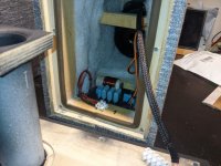
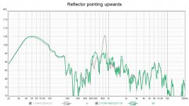
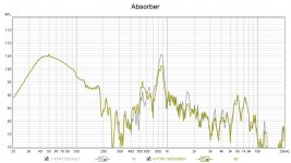
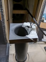
While doing some experiments on my speaker, I placed a piece of plywood in the back of the enclosure behind the woofer at a 45 angle pointing upwards:

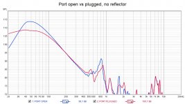
That didn't really change the output of the woofer, which was my original goal, but I discovered that it significantly reduced (smeared) a 850Hz peak I had in the port output.
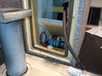
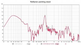
When I flipped this reflector to point to the bottom of the enclosure, that effect was gone and the peak came back.
I also tried putting a piece of high density rockwool in the middle of the enclosure behind the woofer, and the effect was kinda midway between the reflector and no reflector.
(see attached measurements)
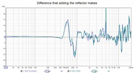
As far as I understand, the reflector changes the path of the wave from the back of the woofer, shifting the resonances to different frequencies, and overall, scatters it around the enclosure.
I'd love to hear your thoughts and explanations, maybe there's a better/easier/more proper way to achieve this?
Also, if you know any good articles on how to deal with the sound inside the enclosure, please share. There is plenty information about stuffing but I didn't find much about the cabinet shape, construction, effects of slanted walls etc.
That didn't really change the output of the woofer, which was my original goal, but I discovered that it significantly reduced (smeared) a 850Hz peak I had in the port output.
When I flipped this reflector to point to the bottom of the enclosure, that effect was gone and the peak came back.
I also tried putting a piece of high density rockwool in the middle of the enclosure behind the woofer, and the effect was kinda midway between the reflector and no reflector.
(see attached measurements)
As far as I understand, the reflector changes the path of the wave from the back of the woofer, shifting the resonances to different frequencies, and overall, scatters it around the enclosure.
I'd love to hear your thoughts and explanations, maybe there's a better/easier/more proper way to achieve this?
Also, if you know any good articles on how to deal with the sound inside the enclosure, please share. There is plenty information about stuffing but I didn't find much about the cabinet shape, construction, effects of slanted walls etc.
Attachments
Correct, though it doesn't 'scatter' anything. 😉 You're now into vented TL theory, so this site is THE reference for TL type alignments: Quarter Wavelength Loudspeaker Design
You can sim it in Hornresp: Hornresp
GM
You can sim it in Hornresp: Hornresp
GM
Could you tell what's the inner dimensions of your box, would be interesting to figure out how that could relate to the peak at ~850 Hz.
edit: btw could you also try make a measurement with the BR port covered, would be interesting how much of the 850Hz is leaking out through the BR port.
edit: btw could you also try make a measurement with the BR port covered, would be interesting how much of the 850Hz is leaking out through the BR port.
Last edited:
Yeah, I forgot to mention, the measurements were made at the port with the mic ~30mm away
Thanks for the links, GM
The port is 170x45mm (6.7x1.8) with 10mm flares on both ends
Thanks for the links, GM
It's 152x245x270mm (6x9.6x10.6 inches)Could you tell what's the inner dimensions of your box, would be interesting to figure out how that could relate to the peak at ~850 Hz.
The port is 170x45mm (6.7x1.8) with 10mm flares on both ends
I think it's caused by a resonance bouncing between the two open ends of the tube: when I was tuning the speaker, as I shortened the port length, the peak would move higher in frequency....would be interesting to figure out how that could relate to the peak at ~850 Hz.
I also made some measurements with the mic on the inner opening of the port.
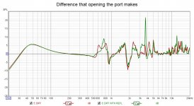
Opening the port creates a bump in the 600-900Hz. Adding the reflector moves the internal modes around, so that there is a peak @600Hz and a null @900Hz
Attachments
The 850Hz ‘ish peak is normal port resonance defined by 344m/s / (0,17m (length of the port)x 2 (half the wavelength) / 0,85 (end correction)) = 860Hz. The deflector obviously does a good job in reducing the air speed at the internal port end though. Interesting!
This is the reason i prefer boxless speakers ie open baffle.
I am using Visaton B200 drivers and have loaded them into the wall, by cutting a hole in the wall so that the Visaton B200 uses the room behind as the enclosure, in my case the kitchen.
Nice colouration free sound, cheap easy and fast
I am using Visaton B200 drivers and have loaded them into the wall, by cutting a hole in the wall so that the Visaton B200 uses the room behind as the enclosure, in my case the kitchen.
Nice colouration free sound, cheap easy and fast
Port plugged, a pipe resonance would disappear as a pipe resonance requires two open ends to happen.
Is the port opposite end of the enclosure as the reflector panel? 850hz resonance would happen with 20cm internal dimension, so maybe it is the port resonance after all.
I guessed wawarad accidentally posted outer dimensions of the box which could make the internal height closer to 20cm. The reflector panel could make another longer "path lenght" to make another resonance to the ~600hz region.
Anyway, pretty dramatic improvement on that peak 🙂
Last edited:
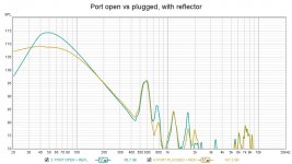
While the peak is not as pronounced on the inside end of the port, there's still some boost around 800Hz when unplugging the port (graph taken from post #6):Port plugged, a pipe resonance would disappear as a pipe resonance requires two open ends to happen.
It's a generic 2 way speaker arrangement with the port on the opposite side from the tweeter. The reflector is below the port, on the opposite side from the woofer. See the photos in the post #1.Is the port opposite end of the enclosure as the reflector panel?
Nah, these are inner dimensionsI guessed wawarad accidentally posted outer dimensions of the box which could make the internal height closer to 20cm.
----
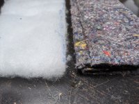
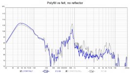
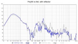
Today I replaced the polyfill lining with a thick felt one, it made a big improvement:
But on the other hand, the reflector is not as effective anymore:
Attachments
From graphs you've posted I'm not reading a pipe resonance. Plugged port (pipe with one end closed) has a quarter wave resonance instead of half wave and could act as an attenuator. I don't have too many DIY speakers under my belt so I'm drawing these conclusions from my primitive physics knowledge 🙂
Could the 850hz resonance be a panel resonance? Is the reflector "touching" the side panels as before when you had different kind of lining now installed? You might be able to "simulate" this by adding a clamp outside the box, squeezing the sides.
It is probably many things that happen simultaneously that make the 850hz peak so pronounced in some configurations and pretty hard to "see" the problem since there isn't one but multiple effects which together show as a problem.
Anyway, best result can be obtained by tweaking like you are doing here. There is no other way get real world improvement than with prototyping!🙂 Have fun!
Last edited:
A damped stub at mid lengh of the port can totally damp first resonnance. It can be approximated easily with hornresp stub mode (SH1, SH2, SH3). I have played a lot with sims around this. Danley did it on commercial product more than 12 years ago with DTS-20, it has been talked a lot here, and there were a nice photo there : Refolding horns, can someone clarify a point ? - Speakerplans.com Forums - Page 2 The photo doesn't work here at work, don't know if this 12 years old picture still works.
With your added panel, you might have haded a damping volume around the problematic frequency. Its like a notch filter, but acoustically, not electrically. Bellow 400 hz, it start to need too big damping volumes to keep realistic.
With your added panel, you might have haded a damping volume around the problematic frequency. Its like a notch filter, but acoustically, not electrically. Bellow 400 hz, it start to need too big damping volumes to keep realistic.
Last edited:
Quick way to test this elimination of port resonance without building proper stub: drill some holes around the port tube at mid length. This prevents pressure node happen there which is needed for the lowest pipe resonance (pressure on the middle and two open ends). This might have some side effects as well, but should show up in measurements if it is pipe resonance that is making the 850hz peak.
Last edited:
Yeah, I forgot to mention, the measurements were made at the port with the mic ~30mm away
Thanks for the links, GM
You're welcome!
FWIW, as a general rule, vent/horn measurements are done inside its boundary layer, so from ~1/4" inside a vent and up to 3/4" for a large horn.
GM
- Home
- Loudspeakers
- Multi-Way
- Dealing with internal standing waves and port leakage