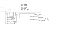
I recently finished a 12B4 preamp that makes a nasty pop when turned on (SS recto, regulated HV & LV PSU, no standby switch). I have decided to add a simple 555 timer/relay circuit to mute the output for 45 sec upon start up.
I breadboarded the 555 timer circuit (see attached), powered it off my bench PSU and it worked great, no issues, nice 45 sec delay.
Next I installed long flying leads from the breadboard and hooked the circuit up to my preamp. At this point I powered the circuit off the amp’s 12V DC heaters.
When the circuit was installed in the amp the relay tripped almost instantly. I believe this is because my 12V heaters are “elevated” and referenced to +40V DC and not ground. The amp’s heaters are referenced to 1/3 of the B+ using a 300K-100K voltage divider. The 100K resistor is bypassed by a 10nF cap. I believe this 100K||10nF that is in series with the 555 timer circuit’s ground is what is screwing up the timing of the circuit.
What can I do to fix this issue? I was thinking of splitting the 300K-100K into 350K-50K-50K and taking the output from the 50K-50K node and powering the 555 circuit off that. Is there another way I can isolate the two circuits/grounds?
Attachments
Did you connect the 555 timer voltage input across the 12VDC heater supply only? I may have misunderstood you but that timer can be left floating. It does not need to be referenced to the amp's ground. Elevating the heater supply shouldn't matter. No need to connect that 555 timer GND pin to the actual preamp ground. Properly wired, that timer doesn't even know the 300K+100k//10nF voltage divider is there.
I have looked at some 12b4 preamp schematics and they seem to connected the heater elevation voltage to the middle of the two heaters (pin 3). One problem with this is that the two heaters never warm up identically so the elevation voltage wanders until the tubes reach full temperature. This may be enough to trigger the 555. You could try not using pin3. Heater elevation is not critical so you could connected the decoupled elevation voltage to either heater pin (4 or 5) and leave pin 3 unconnected.
Cheers
Ian
Cheers
Ian
Yes I connected the 555 timer voltage input (pin 8 and 1) across the 12V DC heater supply only. All the "Ground" connections of the 555 circuit go back to the elevation voltage.Did you connect the 555 timer voltage input across the 12VDC heater supply only? I may have misunderstood you but that timer can be left floating. It does not need to be referenced to the amp's ground. Elevating the heater supply shouldn't matter. No need to connect that 555 timer GND pin to the actual preamp ground. Properly wired, that timer doesn't even know the 300K+100k//10nF voltage divider is there.
The H- node though is referenced to 40V DC though.
Last edited:
I am not using pin 3, heaters are connected in series for 12.6V @ 0.3AI have looked at some 12b4 preamp schematics and they seem to connected the heater elevation voltage to the middle of the two heaters (pin 3). One problem with this is that the two heaters never warm up identically so the elevation voltage wanders until the tubes reach full temperature. This may be enough to trigger the 555. You could try not using pin3. Heater elevation is not critical so you could connected the decoupled elevation voltage to either heater pin (4 or 5) and leave pin 3 unconnected.
Cheers
Ian
- Status
- Not open for further replies.
