

In a pervious post someone suggested using a perforated internal baffle, I did something similar with these, my BBC boxes ( I wanted to make some LS35a clones but it was before I was on diyaudio, so I didn't know what drivers to use- I ended up just using two full range drivers in each box). The red stuff is carpet tile.
If the perforation communicates with the air outside the box would that not be a sort of aperiodic tuning? Only perhaps not as well defined as to more or less completely take down the impedance peak.
The idea I put forward was more similar to the one used in the Dyna example, only with alot of small and various diameter holes so as to have a diffuse or perhaps even non existent "tuning".
Again, I do not know what this would mean for the end result, if it is even beneficial at all, I just thought in terms of energy absorption and diffusion.
One could perhaps also consider having the bracing act as disruptive reflectors if it has sufficient surface are and is arranged/positioned in a beneficial way, maybe assymetrically, but this approach may lend itself better to bigger enclosures.
The perforations were just to damped the rear wave before it hit the rear wall, however I did cut the back of some cheap speakers and used them with a full range to experiment with open baffles, they sounded AUWFUL, because of the resonance with the open back, I stuffed the back with foam to create something like an aperiodic vent, and the sound was transformed, very resonant free.
That's what I did with the tweeter box of my box in a box speakersOne could perhaps also consider having the bracing act as disruptive reflectors if it has sufficient surface are and is arranged/positioned in a beneficial way, maybe assymetrically, but this approach may lend itself better to bigger enclosures.

Hi, few first modes of any box are the most problematic. Higher ones are damped quite easily with damping material and are no problem. Lowest mode can be addressed somewhat by positioning driver(s) acoustical center to the middle of the longest dimension. This works in Hornresp sims and not too deep enclosures (that I've built). There is another thread with impedance measurements of a TG designed speaker Ekta Grande, that has bass drivers approximately at the center height but still there is strong mode visible in the impedance measurement. Enclosure is very deep though. No idea if even that is audible.
Yamaha ns-5000 speaker utilizes some pressure equalization for the lowest modes. Some kind of resonators are almost the only solution to suppress the lowest modes that fit inside the enclosure. Again, higher modes are damped easily with damping material.
Posting this here so I'll get email if any of you come up with a new solution 😀
ps. dual opposing woofers could put acoustic center exactly middle of the enclosure.
If the perforation communicates with the air outside the box would that not be a sort of aperiodic tuning? Only perhaps not as well defined as to more or less completely take down the impedance peak.
Yes. Similar to the straws in the vent or similar that mission had molded into some of their vents.
The vents in my miniOnkens use a simialr principle but are long and high ratio.
dave
One could perhaps also consider having the bracing act as disruptive reflectors if it has sufficient surface are and is arranged/positioned in a beneficial way, maybe assymetrically, but this approach may lend itself better to bigger enclosures.
Something like this?
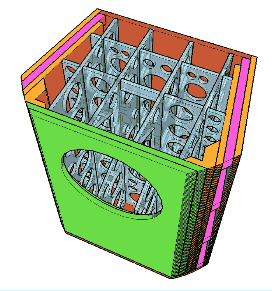
There is no straight path thru the holes in the braces from side-to-side and back-to-front. The holes are not small enuf fto impede LFs.
dave
Hi, straight or curved path shouldn't matter otherwise bending a TL or other bent horns wouldn't work. Obstructions only make longer paths inside the enclosure lowering the modes even further making them even harder to mitigate. Nevertheless, all this might not matter at all if they are not audible. Unnecessary amount of work and material in my engineering point of view to do such complicated internal structure with questionable motive 🙂
edit. you could introduce some 1/4 wave resonators inside the enclosure with bracing, which should work maybe. Prototype time!
edit. you could introduce some 1/4 wave resonators inside the enclosure with bracing, which should work maybe. Prototype time!
Last edited:
I wonder if anyone has made an active back wall for a speaker cabinet? A second speaker behind the first that, instead of presenting a stiff boundary like a piece of plywood, it absorbs some of the front speakers back-radiation in the problematic frequency range.
What goes behind that speaker? A small sealed box. Thinking a more expensive speaker facing the listener and a less expensive driver for the "absorber" part. Will require an extra pair of channels to drive the absorbers and HP and LP signal filtering.
You should research 'Isobaric' speakers - there were several made on exactly this principle. No need for seperate amplifiers, the inner drivers were supplied with the same signal.
Looks like a tapered half-wave midTL (Not the simpliest way to do it. How low is thw XO? What tweeter are you using that it needs a box?
dave
Hi, straight or curved path shouldn't matter otherwise bending a TL ...
It depends on the wavelength of the frequencies you are talking about. Certainly LF do not see the folds, and such, as the wavelengths approach the size of the structures involved then teh structure starts to affecty them. For instance why it is usually counterproductive to add deflectors to the bends in a TL or bass horn.
dave
Looks like a tapered half-wave midTL (Not the simpliest way to do it. How low is thw XO? What tweeter are you using that it needs a box?
dave
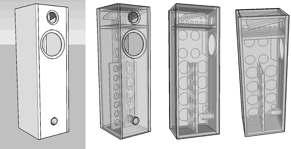
I think the picture is a bit misleading, the bass box is aperiodicly loaded ( by vents in the rear ) into the main enclosure, the " tweeter " is actually a small full range cone driver, and it's tweeter box is supposed to be like a taper ( like nautilus ) but folded into a cube. The crossover is first order, about 2,500 Hz ( the full range tweeter driver drops of bellow that, so I thought that I'd use that to advantage ). The whole idea was to have two separate internal enclosures, isolated from the main enclosure by foam and springs. If you search for biab you might find more on it in the multi way section.
Except terminus instead of boundaries, a short heavily tapered quarter-wave line.
dave
A proper TQWL can work extremely well. Thats one thing b&w actually got right to some extent. Their nautilus series took that to a whole different level with skeptical results.
I always prefer to treat the resr wave with an appropriately shaped and designed enclosure first while relying on dampening materials to take care of most higher order modes, otherwise as I said before, you risk overdampening the fundamental mode that can suck the life out of the first order resonance.
In my earlier open baffle designs I would try all sorts of things to get rid of most rear wave energy, but I realized that turned the open baffle into a critically damped design which defeated the purpose of an open baffle. Unless higher Qts drivers were used, that would lead to a dull and lifeless sounding speaker.
I built a few TQWLs in my beginning years that were inspired by the larger Quadral Titan and Vulcan speskers which were all the rage in Europe in the mid 80s. They sounded really good for that era and the low end capability was not common for those days. As you probably know, the challenge with that type of enclosure is strategic and judicious use of dampening materials in multiple areas. Thats not easy to get right, even with today's simulation software.
I also had a hell of a time trying to dampen the upper enclosures in my Manger 109s. The MSW driver is very sensitive to mechanical (over)dsmpening and depends on the primary resonance mode to be unimpeded in order to play low enough and integrate properly with the LF driver. I probably messed with cabinet dampening for 2 weeks to get it sounding right. Once it was dialed in, the driver sounded very natural and full bodied. That also fixed alot of the 1k-ish looseness others complain about with this driver. The solution that worked best was building up a tennis ball with decresing density dampening material and placing it 5 inches behind the MSW.
Last edited:
I would be leary of venting it into the same enclosure as th ebass driver.
Given the holes, it becomes quarter-wave so length should be good.
A fold like this achieves essentially the same thing easier. In this case half-wave, but the planset this is from has many variations,
the midTL in this planset come sin a number of varieties.
dave
Given the holes, it becomes quarter-wave so length should be good.
A fold like this achieves essentially the same thing easier. In this case half-wave, but the planset this is from has many variations,
the midTL in this planset come sin a number of varieties.
dave
A proper TQWL can work extremely well. Thats one thing b&w actually got right to some extent. Their nautilus series took that to a whole different level with skeptical results.
It can. It has to be about 2x as long as a quarter wave.
...Vulcan speskers
The modern version:
dave
"Nevertheless, it is common practice to mount sound absorptive
layers directly against a wall, because it is very convenient to do so.
We must, however, realize that, in such cases, only the outer one-third of the thickness of the layer is effective in absorbing sound.
The rest of the material is simply acting as a convenient support!
Therefore, the values of R/rc for the 1/2" layer of material
given in Table 4, and the corresponding values of amax, assume that
this 1/2" layer is mounted near the perforated metal screen with, say,
an inch of empty airspace behind it. so that the entite 1/2" layer is
effective.
If the layer were mounted directly against a hard wall, the
tabulated values of R/rc would have to be multiplied by 1/3, and the
corresponding values of maximum absorption recalculated."
from: http://www.iperf.org/files/1313/9265/8912/The_Acoustical_Uses_for_Perforated_Metals_Handbook.pdf
I would put some air space between the felt and walls. If you have an issue at one frequency, make a tuned perforated plate to that exact spot.
As spladski said, tiny chambers are a good idea. According to the paper in increased the bandwidth and angle of what the box will catch vs a flat wall.
Yes, Pete, the Yam contains two J-shaped resonance tubes or "Acoustic Absorbers".
They work on the same principle as the exhaust pipes in automobile exhaust systems which are designed as acoustic resonators to reduce noise by "sound cancellation".
They work on the same principle as the exhaust pipes in automobile exhaust systems which are designed as acoustic resonators to reduce noise by "sound cancellation".
- Home
- Loudspeakers
- Multi-Way
- Dealing with a driver's back wave energy.