An active absorber is probably best described as having a microphone, an amp and a speaker. Whatever is heard by the mic is played out of phase by the speaker. If done right this makes nearby sound go away, so it is similar to damping material.Like a passive radiator then ?
How would this affect sensitivity?An active absorber is probably best described as having a microphone, an amp and a speaker. Whatever is heard by the mic is played out of phase by the speaker. If done right this makes nearby sound go away, so it is similar to damping material.
Wouldnt that make it sound weird? 😉Filling it with helium could make your idea take off! 😀
I wonder if anyone has made an active back wall for a speaker cabinet? A second speaker behind the first that, instead of presenting a stiff boundary like a piece of plywood, it absorbs some of the front speakers back-radiation in the problematic frequency range.
What goes behind that speaker? A small sealed box. Thinking a more expensive speaker facing the listener and a less expensive driver for the "absorber" part. Will require an extra pair of channels to drive the absorbers and HP and LP signal filtering.
Buchardt S400 uses Passive radiator, puts the energy in backwave to good use..
Discopete, if it were able to do the same job as the damping material then sensitivity shouldn't be affected. It isn't there to supplement the main driver and make it more or less loud.
On the other hand if you do it a certain way you can make the box seem larger or smaller, and this would affect the bass output.
On the other hand if you do it a certain way you can make the box seem larger or smaller, and this would affect the bass output.
Could it be implemented this way?It isn't there to supplement the main driver and make it more or less loud.
Of course, you could have a driver that is producing some of the wanted signal and an error correction signal at the same time. The simplest form of that is to just have the one original driver and add EQ to it.
Or did you mean something else..
Or did you mean something else..
Which is ultimately better? Would there be the advantage of a stiffer piston due to the second cone and thus lower distortion/better extension?
In what way, I mean how do you envision this reducing distortion and increasing extension.. or are you trying to describe one partucular configuration and if so, what is it?
Edit: or are you asking me to expand on what I said earlier about varying the apparent box size?
Edit: or are you asking me to expand on what I said earlier about varying the apparent box size?
Sorry, just generalizing. You seem to be quite knowledgeable. I'm picking your brain😀 I guess I'm suggesting an isobaric configuration where the drivers responses are not the same as a possible advantage to the accepted science.
You will have a SLIGHT slowing with no practical effect whatsoever.l
Very small. Not worth talking about. The damping acts as a resistance, but not to the speed of sound. It absorbs HF. As it gets thicker how high moves down in frequency.
dave
I have thought about putting a second thin but braced perforated internal baffle roughly halfway along the inner depth of the enclosure, or diametrically oriented between the inner corners, the perforation would be made by ~10mm holes the number of which would sum up to ~ the same area as the drivers Sd.\
Given that Sd only tells you how big the cone is, it is not an appropriate thing to base the restriction on.
This is more or less what the Dyna A35/A50 did, and many of the NAIM boxes. Likely dates well before that. Someone pointed out just today that someone beat Jordan to aperiodic some 2 and a half decades earlier. Your suggestion is a variation.
dave
I wonder if anyone has made an active back wall for a speaker cabinet?
ou mean a dynamic isobarik. Instead of running the same woofer with the same signal, one uses a DSP filtered signal for the back driver (same o “bigger”) to dyanamically change the lad for the front woofer. Been doing thou experiments since the late 80s.
dave
Glad to help. 🙂Sorry, just generalizing. You seem to be quite knowledgeable. I'm picking your brain😀 I guess I'm suggesting an isobaric configuration where the drivers responses are not the same as a possible advantage to the accepted science.
An isobaric configuration would be inclined to present a blend of the responses of the two drivers acting differently, and would do that up to the point where the gap between the cones is too large to couple them simply at those higher frequencies. Then their effect would become difficult to predict and they should probably be crossed before then
Up until then, the result would be similar to a single driver with added EQ.
Damping a driver playing midrange frequencies isn't as simple as you would think just using foam, dacron fiber fill or similar materials by themselves. The best approach is a gradual increase in density approaching the cabinet boundaries, by layering the dampening materials. My favorite dampening mediums are open cell poly foam, mostly for ported cabs and good old tried and true sheep's wool. I sometimes use wool felt on the cabinet walls behind lower density wool or dacron.
Using a denser, flat faced dampening material close to the driver actually can result in unwanted resonances and standing waves at lower midrange frequencies that are undampened and reflected back at the cone backside. The result is usually heard as a muddy, canny sound and can make the driver behave worse than just light dacron stuck to the cabinet walls.
Getting the most wide range absorption is key to making the driver sound as inert and unaffected as possible by the enclosure while retaining a decent amount of low end response. If you overdo the dampening, it will excessively kill the low end output of the driver (greatly decreasing system Q), sometimes making the driver sound lifeless - kind of a critical thing to get right with smaller midrange drivers so they can play low enough to gel with the LF driver.
You do get ripple as the distance from driver 1 to driver 2 approaches those wavelengths, limiting HF extention.
dave
dave
a gradual increase in density approaching the cabinet boundaries
Except terminus instead of boundaries, a short heavily tapered quarter-wave line.
dave
This is more or less what the Dyna A35/A50 did, and many of the NAIM boxes.
I have heard that the main boxes used something similar but I had not heard about the Dyna speakers before, thanks, I checked them out quickly, seems to be a slot, or soppubly several slots, quite large, into a another closed volume, sort of like a helholtz trap but I will look into it more.
My thought was to have alot of small holes that when combined would not strive to have a specific tuning, it would instead act as a slight flow restriction if you will, for example it could consist of 2x20mm & 20x15mm & 20x10mm holes, an acoustically semi transparent divider of sorts, and it needs to consider driver displacement capabilities.
I have been designing and building speakers long enough to know that there is sadly rather little left to actually discover of invent, most things has been done before, but nowadays our tools and equipment has evolved, as has the drivers, which might merit a revisit of some of the old stuff that did not take off at the time due to the limitations at play at that time.
Not saying this thought of mine is such a thing, nor would I claim any credit for it, for the same reasons 🙂
Last edited:
A drawing i did of the A35
Holes can be very useful. Besides providing some damping themselves it provides an ideal surface againsy which to push damping.
The PEARL PR2 is a good example. A LOT of work went into getting the loadin right.
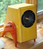
I used the same technique to really good effect with a 4.5 litre enclosure for the CSS FR125.

Not our build, this one is prettier. A set of holes near th ebottom on the back with open cel foam pressed against it.
dave
Holes can be very useful. Besides providing some damping themselves it provides an ideal surface againsy which to push damping.
The PEARL PR2 is a good example. A LOT of work went into getting the loadin right.
I used the same technique to really good effect with a 4.5 litre enclosure for the CSS FR125.
Not our build, this one is prettier. A set of holes near th ebottom on the back with open cel foam pressed against it.
dave
Attachments
- Home
- Loudspeakers
- Multi-Way
- Dealing with a driver's back wave energy.