Hi everybody,
After your great help with the nad 314, I got some appetite and got myself a new challenge: a dead Onkyo tx-sr500e.
The receiver is totally dead. I plug it in, power it on, but nothing happens: no display, no led, no relay-clicking. Absolutely nothing.
Naturally, the first suspect was the power supply.
The fuses are ok, and there is no visible sign of blown components.
I noticed a small transformer on the power board (in addition to the big transformer which I believe supplies the power to the analog section)
Is it possible that there is a "secondary" power supply (switching power supply?) for running the digital electronics? If so - is it reasonable to assume that this switching power supply is faulty?
Where should I look? I'm kinda scared to start poking my multimeter in the 220V area 🙂
Any help/clue would be much appreciated.
Thanks,
- Barak
Onkyo usually has voltages on the small standby-by supply board. You will need ~5.0-5.6V constant, without it only plugged in and not on “stand-by” mode.
If you have this voltage, then see if you can unhook the amplifier board(s) and try to power on. If it will power up then, you know it’s the protection circuit keeping it off.
Try these “carefully” with your DMM and report back.
If you have this voltage, then see if you can unhook the amplifier board(s) and try to power on. If it will power up then, you know it’s the protection circuit keeping it off.
Try these “carefully” with your DMM and report back.
The small transformer belongs to the standby power circuit. It enables the main power supply to be switched on using a relay.
The first tip in the manual is to replace the batteries in the remote with fresh ones.
ONKYO TX-SR500 Справочник Пользователя - Страница 1 из 40 | Manualsbrain.com
The first tip in the manual is to replace the batteries in the remote with fresh ones.
ONKYO TX-SR500 Справочник Пользователя - Страница 1 из 40 | Manualsbrain.com
Last edited:
Thanks for the fast responses!
bullittstang - I didn't understand what to do. Should I take out the standby power supply board and try to power with a bench power supply?
Here's what I've done so far:
I downloaded the service manual, and it looks like the standby pcb should output 13V.
I disassembled the stby board from the amp board and measured voltage at the output.
When power is off (physical power switch) - it outputs 0.5V. When I press the power button - my DMM shows 23V. It should read 13V, shouldn't it?
I'm measuring between MPUGND and +13VS pins on the output conbector.
Does this mean that that stby pcb is faulty?
Thanks in advance,
- Barak
PS: I don't have the remote...🙂
I would start by testing diodes and resistors on the standby board. Sounds like there might be a zener that is shorted allowing full 23v instead of 13v to the relay?
I haven’t looked at the service manual, so would help if you added a snip of that part of the schematic here.
I haven’t looked at the service manual, so would help if you added a snip of that part of the schematic here.
bullittstang, thanks a lot for your willingness to assist! I really appreciate it!
I'm attaching the schematics of the stby-pcb from the service manual,
and also a zipped version of the service manual PDF (I hope this doesn't violate the forum's rules).
The stby-pcb is the It's the U20 module.
Is there a way to test the components while in-circuit? I wouldn't like to start disassembling everything 🙂
BTW - I failed to find a Zener diode on the pcb (but I'm a newbie, so I might have just missed it).
Again, thanks a lot!
- Barak
Attachments
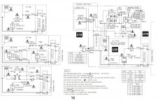
Caution! You will be working with a 120v AC electrical circuit. Voltage is supplied to the main transformer through the contacts of relays, POWER button and a fuse.
U20 contains a transformer, a 13V unregulated rectifier, a relay and a switch that controls the relay. The key is triggered by the POWER voltage from the main power supply unit.
Voltage 13V is used to power the start circuit and protect the main part.
U20 contains a transformer, a 13V unregulated rectifier, a relay and a switch that controls the relay. The key is triggered by the POWER voltage from the main power supply unit.
Voltage 13V is used to power the start circuit and protect the main part.
Last edited:
Thanks for the warning, OldDIY. I undrstand that this is a dangerouos area and I'm taking extreme caution.
The question is whether I'm searching in the correct place. Should the stdby-pbc produce 23V when unloaded?
If not - what should be my next steps?
Here's what I've done so far:
There are a few 0.1 microfarad on the board, but I can't check them in-circuit since my esr meter can measure 1 micro and up.
I tested the 220 microfarad electrolitic capacitor and it tested ok. The transistor that triggers the relay also seem to be ok (I tested b-e and b-c conductivity and they conduct in the correct way).
Any idea would be appreciated.
Thanks,
- Barak
Measure the AC secondary voltage on a small transformer. The DC rectifier voltage can be 1.4 times higher. If the bridge diodes are faulty, unwanted voltage doubling can occur.
Identify and check all parts of the startup circuit (not just the U20).
Identify and check all parts of the startup circuit (not just the U20).
Hi again,
The AC voltage on the secondary transformer is 17.2V
The voltage on the output, after rectification is 23V
Does this mean that the transformer is faulty?
Thanks,
- Barak
The AC voltage on the secondary transformer is 17.2V
The voltage on the output, after rectification is 23V
Does this mean that the transformer is faulty?
Thanks,
- Barak
Yet another update:
I tried feeding the standby circuit with an external 13V dc transformer (thus bypassing the small transformer and rectifier), and the device did not power.
I measured the voltage at the pwr node (pwr to gnd) and I got a constant 1.6V. When I press the standby/on button, it goes up to 1.8V.
I think this voltage goes into the small transistor on yhe stby board, which (I believe) should drive the relay that sees the party.
As before, any hint will help...
Thanks again,
- Barak
# 10 If the transformer is correct, then the voltages are correct.
The circuit works in conjunction with other amplifier circuits. Check separately the serviceability of the transistor and relay (if you close the с-e it should work).
The diagram shows the voltages across the transistor.
The circuit works in conjunction with other amplifier circuits. Check separately the serviceability of the transistor and relay (if you close the с-e it should work).
The diagram shows the voltages across the transistor.
Last edited:
- Home
- Amplifiers
- Solid State
- Dead Onkyo tx-sr500e (newbie's question)