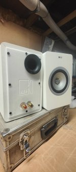
Greetings Blach, Galu, and other happy Modifiers!Btw. as I don't need them anymore and cannot fix it anyways: If anyone is interested in the KEF x300a electronic parts, please let me know.
I'm in Europe/Austria.
Thanks for the great information in this thread. I am inspired. I'd also like to explore a slightly different tack.
I'd be interested in obtaining a set of the unused / discarded X300a innards for the purpose of experimentation. If anyone still has these parts lying around, please contact me.
Cheers!
Hi, bought Kef X300A Wireless used that had a modified input arrangement, where RCA plugs were added each side. I'll try to include some photos for reference so others could try to replicate. Worked flawlessly for two years or so. Now have the issue that one is much quieter then the other.
Neat. I've read of someone long ago providing a service to hack in an RCA output for a subwoofer. How many RCA connectors were added to each of your speakers, and what exactly is their function?Hi, bought Kef X300A Wireless used that had a modified input arrangement, where RCA plugs were added each side. I'll try to include some photos for reference so others could try to replicate. Worked flawlessly for two years or so. Now have the issue that one is much quieter then the other.
Did the person who added them give you schematics of the modifications? Have you ever them open and looked aound?
As far as one unit being quieter than the other: Is this still true for louder levels? Does that quiet speaker sound relatively clean at lower levels?
I ask those two questions because I have one slave speaker that sounds OK when played loud, but at low levels (after a couple of hours) sounds a bit... crunchy. I suspect that one of the amplifiers' output bias may have collapsed and I'm hearing output transistor crossover distortion. The unit is in a dozen pieces right now, waiting for a powered diagnosis...
Looking forward to photos!
Somehow the photos were not included, let's try again.
As said, I opened them because the "LEFT" one started become more quiet and noisy. After switching the power supplies between the two I suspect it's the power supply that is acting up. I don't see any bulging capacitors, but did see there was some bypass done on the relay, so it's not the first time the power supply has issues. This relay connects the AC 230V to the toroidal transformer.
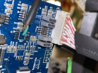
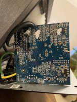
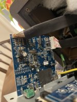
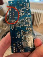
This is basically the changes by the previous owner to the signal path I believe:
RCA connector on the back of the speaker, connected to the top of the DAC board, hopefully before the signal is digitalized and the DSP does it's job (is there a DSP here?). Then there is a capacitor added on the backside of the DAC PCB board. And there is cable running from the front to the back.
I am not sure what the reasoning behind it is, but I guess it's bypassing the S/PDIF signal coming from the main, "RIGHT", speaker?
To be honest, I am considering just putting either a passive filter like shown in this thread or a minidsp in them and connect it to 2 TPA3118 board each. Would be great if the power supplies and toroidal transformers could be reused then...
Attachments
Last edited:
Beware
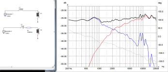
Beware original schematic shows Tweeter is connected out of phase with wooferSince you say you're not familiar with the software layout, I've attached a schematic which shows clearly how the crossover circuit is wired to the speaker input terminals.
The resistor is not shown, but you'll know where to put it! 😎
T
We are in 2024 and is STILL appearing in my feed.
As of my correction comments, everybody can have his own opinion or taste, but I feel obliged to comment on dangerous suggestions such as the 47uF capacitor which would have blown an EXPENSIVE coaxial speaker.
Making the remaining cabinet useless since user needs a matching Stereo pair.
Are you aware of the damage such a "simple" but WRONG suggestion can do?
This old post keeps raising its head over and over.See post #13....I posted the values on my car speakers.
Suddenly you remember a six month old post?
What happened?
We are in 2024 and is STILL appearing in my feed.
As of my correction comments, everybody can have his own opinion or taste, but I feel obliged to comment on dangerous suggestions such as the 47uF capacitor which would have blown an EXPENSIVE coaxial speaker.
Making the remaining cabinet useless since user needs a matching Stereo pair.
Are you aware of the damage such a "simple" but WRONG suggestion can do?
Beware original schematic shows Tweeter is connected out of phase with woofer
Correct, the software schematic shows the required phase inversion whereas my simplified diagram did not.
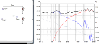
Since we're so far on into the thread, I think it best to attach the software schematic again, as well as include the verbal description I gave earlier.
Woofer section
Signal Out: amplifier positive to inductor to woofer positive
Signal Return: woofer negative to amplifier negative
Tweeter section
Signal Out: amplifier positive to capacitor to resistor to tweeter negative
Signal Return: tweeter positive to amplifier negative
Attachments
Fascinating, Captain... This looks like:Somehow the photos were not included, let's try again.
- 100uF/25V in place of R168, at the input of the low-pass crossover filter. Maybe to try to get rid of a DC offset?
- Connections to U108: Note that U108 (mono switch) has been removed. U108 connects the "Cut" filter that's switched in when "Desk" is selected via the back panel switch. Its removal means that signal is no longer making it from the USB Audio -> SPDIF receiver -> DAC source. The green/brown wires shown connect line level input to the output of U108 - immediately before the crossover.
- Connection to J201:10. I think this connects to the relay on the amplifier board, and is connected to a regulator (U106) to override the speaker relay control that ordinarily comes from the micro (U301)
It's possible the main filter caps on the power supply are stressed and flagging. At 2200uF, they seem small for a 50W+20W amplifier.As said, I opened them because the "LEFT" one started become more quiet and noisy. After switching the power supplies between the two I suspect it's the power supply that is acting up. I don't see any bulging capacitors, but did see there was some bypass done on the relay, so it's not the first time the power supply has issues. This relay connects the AC 230V to the toroidal transformer.
...
To be honest, I am considering just putting either a passive filter like shown in this thread or a minidsp in them and connect it to 2 TPA3118 board each. Would be great if the power supplies and toroidal transformers could be reused then...
Certainly it sounds like this group has had great success in hacking in a well-thought out passive crossover, and that should sound great.
One idea I've been toying with is to reuse only the dual amplifier:
- From an external LF/HF crossover (analog or digital),
- Feed LF/HF line level via RCA connectors on the back directly to the amplifiers
- Replace the power supply with something much simpler and beefier
Switched input boards and power supplies over from the good to the bad speaker, still have the issue of static noise and less low-frequency sound. So the issue is probably on the AB amplifier side.
Also, noted that the relay of the power supply was bridged.
Also, noted that the relay of the power supply was bridged.
Attachments
Last edited:
A customer had a dead pair of these and linked me to this thread.
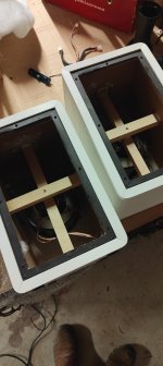
I removed all the internals and sealed all the bolt holes and the little led one on the front, added the cross braces, lined the walls and installed the crossover from Galu.
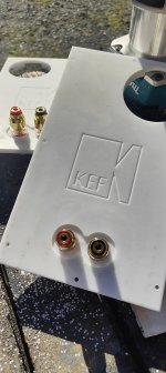
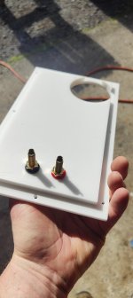
I machined new back panels and reused the ports and installed new binding posts.
Customer was very happy!
Thanks for this thread 👍
Attachments
...and installed the crossover from Galu.
Since the thread has been re-opened, I shall state that its original purpose was to convert the active KEF x300a loudspeaker to passive use.
The solution is to use the KEF Q100 crossover circuit, the schematic of which is attached.
P.S. That is a beautifully executed job @spacies
Attachments
I've wondered this myself. The whole design, inside and out, with the exception of the SP1587 driver, looks a bit "non-KEF", as though it was a rapid development with some external design help. Its look isn't consistent with other KEF products of the time. The initial revision even used an FPGA: hardly a building block of mass-market product!I am very surprized that there is so many failures on these speakers by KEF. They are supposed to be a competent company/ But I am guessing that a speaker company may not be an electronic company. Guys, you should find yourself someone that can design robust electronics.
One of the things that struck me about a (slave) X300A that started to sound wonky was a graininess only at very low levels. Almost as though the main output bias had gone way out of spec, and I was hearing large crossover distortion. I have the guts of that unit all over my workbench, waiting for me to customize a bit of a wiring harness to hook it all up and try to diagnose it properly.
- Home
- General Interest
- Everything Else
- Dead KEF X300A - what to do with them?
