I was wondering if someone would be willing to teach me to trouble shoot a McIntosh Amp MC300
I am semi-literate in electronics and have a fair amount of diagnostic gear.
One channel is not working.
It has a protective mechanism called "Power Guard"
It essentially shuts down a channel when it detects distortion.
Does this forum allow me to post a link to another sites that has good pictures of the inners?
Attachments
Last edited:
Most commonly dead channels in amps over 15 years old are oxidation of contacts. Internal connectors, input connector, should be power off disconnected and reconnected. Volume pot wiper, tone control or balance pot wiper, should be exercised and later checked with an ohmmeter to the end of the pot. I've had to replace some of these on my old equiment, especially volume. Input cables are suspicious, swap the channels to make sure the source is putting out on both, and the cables are sending music on both channels.
Next input caps often go bad, the MC250 doesn't have them, but if this does, those little tantalums or electrolytics (4.7 to 10 uf) are suspect over 15-25 years old.
Third common problem, a speaker wire short could have blown the output transistors. Look for DC voltage on the speaker terminals of the dead channel. If so, there us usually more blown than just the output transistors. Emitter resistors and driver transistors should be checked.
Some old macintosh have transistors in sockets, with power off these should be removed and replaced.
Not fixed yet, get a schematic from eserviceinfo.com, or another site a search engine can find you.
get a dvm. I use the craftsman non-autoranging one so I don't have to wait for it to sequence up to the 20 or 200 v scale, every time. Remove rings, jewelry, learn the one hand at a time rule to not kill yourself electrically.
Power on, look for stupid voltages. Mains caps not having 80% of the rating on them. diodes not having .6 v forwards or a higher voltage backwards. Film caps having the same DC voltage on both ends. Transistors not having .6 v forwards b-e on npn or -.6 v on pnp. collector voltage not between 3/4 and 1/4 of the power supply voltage. Voltages at two ends of a wire/trace not being the same.
Cold Resistors having more voltage drop than the power rating would allow.
If you find and correct some problem see this thread for checking idle current etc before buttonning up: vintage amplifier repair/upgrade manual - diyAudio
If the Dc voltages are plausible and sound doesn't pass, get a transistor radio with earphone jack and an analog VOM with 2 vac and 20 vac scales. Exercise the input with the radio, see how far the sound gets. On a rock station, you can see the beats kick the needle in rhythm. Don't use a cell phone, amp faults can blow it up with DC feedback. I use a pocket battery tape player from the trash with one dead channel. Listen first to get the radio on a station. I use a 1/8" stereo phone plug to double RCA male adapter available from newark mcmelectronics or someplace. Protect the negative meter probe with a .047 uf 200 v cap or similar, VOM can read AC voltage on just plain old DC unless you block it off. I use clipleads for this, same source. Or get a scope, which is harder to learn to usse. Find out where the music disappears.
Examine that stage carefully.
When you find wrong stuff, report back if you can't figure it yourself.
Best of luck.
Last edited:
The protect mechanism usually looks for DC on the output.
If there is DC on the output then possibly output transistors are blown.
You need to look up testing transistors on the net with a multi-meter.
As previous post also check driver transistors and other discrete's around driver/output stage.
If there is DC on the output then possibly output transistors are blown.
You need to look up testing transistors on the net with a multi-meter.
As previous post also check driver transistors and other discrete's around driver/output stage.
Thank you both. I will do as you say.
I would be up to checking out all the HOTs. I have uploaded the schematic on my first post. I have pictures of this unit but its on another web site. Are there rules about posting links on this forum? I want to make sure that I do my work safely and there is one area I want to keep away from and would like some advice on it.
I would be up to checking out all the HOTs. I have uploaded the schematic on my first post. I have pictures of this unit but its on another web site. Are there rules about posting links on this forum? I want to make sure that I do my work safely and there is one area I want to keep away from and would like some advice on it.
Sorry but it´s an old, very good, very complex amplifier, the schematic is hard to read and circuit is split into many small blocks, which *are* interconnected but that´s not quite clear as shown.
Plus it´s not a conventional amp, unlike 99.99999% of SS amps out there this one has an output transformer (sorry Nigel but never DC on *this* amp output, even if blown to pieces)
What´s my point?: it can be repaired by a *seasoned* and experienced Tech, not the best to cut one´s teeth on, I´d send it out to repair.
Sorry.
If you have problems with another, say more "normal" amp, we will be glad to help, but I fear this one will be frustrating, for both parties involved.
Okay, no picture requied. The schematic has enough layout info.
You have 10 and 22 uf coupler caps on input board and power board. These age badly.You have interboard connectors, between input board, driver board, output boards. Need reseating. You have pots with wipers in the input circuit, not to mention the meter etc. Need wiggling, maybe spraying off, maybe replacing. All of these are suspicious parts to cause dead channel.
I don't see a protection relay , that often causes silence due to oxidized contacts. The relay I saw is a power on relay, 120 vac has no trouble burning through oxide. If you do have protection relay that passes music voltage, either dc or a bad part has tripped the detect circuit and opened the contact, or oxide is keeping the music from getting through. The latter is common.
I'd address those before handing $300 to Mr. Electronics Expert service. Many tend to charge 75% of new price whatever they actually do. I worked in a camera repair service for 6 months, got sick of their practices and went into industrial maintenance. USA is not a low cost labor area. Most consumer electronics goes to the dump and gets replaced with new import trash.
BTW an output transformer will protect your speaker from DC voltage out, but if a shorted speaker wire blew the output transistors, the DC would show up at the input of the transformer, not at the output.
Note op amps used in analog (the trangles) should idle have about the same DC voltage going in, as going out. Radical differences can be corrosion between pin and socket, or in the case of my PA amp, a bad solder joint on the socket to board made at the factory in 94. Not found until I bought it in 2012; multiple techs had been in there replacing output transistors and finally labeled the jacks "do not use channel A" and unplugged the power to the channel. What professionals. This tiny little town only has 2 million inhabitants, not big enough I guess to support a competent repairman.
Last edited:
I plan to see If this is something simple before I reflexively lug this thing to an expert.
The only thing that concerns me is human injury. I could send pictures of this (but on another web link) and maybe I could keep away from the - and + rails but I am not 1000% sure where they are. Don't let this ignorance deter you from giving me future advice out of fear I will kill myself. I am humble and learning but I have been learning for a long time
The only thing that concerns me is human injury. I could send pictures of this (but on another web link) and maybe I could keep away from the - and + rails but I am not 1000% sure where they are. Don't let this ignorance deter you from giving me future advice out of fear I will kill myself. I am humble and learning but I have been learning for a long time

Touching the rail voltage with dry skin with ONE hand is mildly painful, not dangerous. NO RINGS No dangly neck jewelry. Keep other hand in pocket, not touching the chassis or any other bare metal. It is current flowing across your heart that is dangerous, or jewelry will cause unlimited current to the skin that touches it that can cause major burns.
clip the meter negative to signal ground (like RCA jack ring) with an aligator clip lead, use one hand only to probe around with the other.
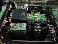
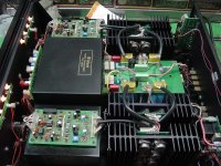
Those diamond shaped transistors have rail voltage on the tops. I don't see the big round rail capacitors, those have rail voltage on one terminal. Possible the 120 VAC relay is on the board barely visible on the lower right, it does have a big power resistor.
I see a relay on the lower left board, the relay I saw on the schematic has 120 vac going to the contacts.
Not if unplugged.
The big round rail filter caps store current possible even if unit is unplugged. They go to the output trnasistors, so don't unplug the latter unless voltage on filter caps is < 1v. Read the high voltage safety thread under tube amp forum to see a cap discharger. I use a 47 ohm 5 watt resistor between two clip leads myself. smaller plastic covered e-caps also can retain voltage, but the amount is not major below 220 uf in speaker drive amps.
clip the meter negative to signal ground (like RCA jack ring) with an aligator clip lead, use one hand only to probe around with the other.
Those diamond shaped transistors have rail voltage on the tops. I don't see the big round rail capacitors, those have rail voltage on one terminal. Possible the 120 VAC relay is on the board barely visible on the lower right, it does have a big power resistor.
I see a relay on the lower left board, the relay I saw on the schematic has 120 vac going to the contacts.
Not if unplugged.
The big round rail filter caps store current possible even if unit is unplugged. They go to the output trnasistors, so don't unplug the latter unless voltage on filter caps is < 1v. Read the high voltage safety thread under tube amp forum to see a cap discharger. I use a 47 ohm 5 watt resistor between two clip leads myself. smaller plastic covered e-caps also can retain voltage, but the amount is not major below 220 uf in speaker drive amps.
Last edited:
"It essentially shuts down a channel when it detects distortion."
Incorrect.
Power Guard is an input/output comparator that drives an LDR (light dependent resistor) input attenuator. It is not likely to be the cause of the problem.
Incorrect.
Power Guard is an input/output comparator that drives an LDR (light dependent resistor) input attenuator. It is not likely to be the cause of the problem.
Furthermore, wear safety glasses when powering up amp after replacing components. Weak over stressed transistors, and e-caps installed backwards, can explode.
To prevent transistor explosion, if you replace some shorted ones, power back up on a "light bulb" limiter box, a 100 W old fashioned incandescent bulb in series with the AC power coming in. These are no longer for sale in USA, the halogen replacements have some sort of diode in them. A coffee cup immersion heater in water might be a suitable replacement. On big amps I use a heating element from a dead 1200 w room heater series the AC in, that conveniently has spade lug connections to it. I used insulated spade lugs from dorman (auto supplies elec dept)
E-caps, mark the board or flying wire with a sharpie on the plus, to avoid putting in backwards. On a flying wire to a screw terminal cap, make a tag with scotch tape to write on.
Update:
Having the assistance of a certified tech help me keep safe and teach me. Progress is slow because of our schedules but here is an update.
Found a dead driver transistor in the right channel MJ15020 Q18 and replaced
All other transistors in right channel checked out ok.
Found blown resister r50 and replaced
Retested:
amplifier worked well at low volume but power guard came on again right channel
We then connected to distortion analyzer with dummy load
Within seconds: smoke and Driver q18 literally caught fire.
I ordered all new components for PCB 047188 and replaced them and then powered up again
Discovered that the stereo mono mode switch did not work and had a burnt trace: fixed
When signal inputted to left channel the oscilloscope showed a nice wave form and no right output signal
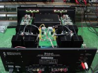
When signal applied to right channel and low amplitude there was a nice appearing signal but has volume increased, a whining noise was heard coming from the right autoformer and the right heatsinks became a lot hotter than the left ones did.
Oscilloscope also showed wave forms coming from the left terminals even though signal was being applied to right only.
Considered issue was coming from the input board 048488 since there was a trace burnt on that board. Tested both opamps by replacing but this did not fix.
Swapped left and right power driver pcb boards but this did nothing
Took left heat sinks and all their components and put them on the right side and made sure I connected properly and the left heat sinks when put on the right side did not remedy the problem and the left heat sinks become hot and noise stayed within the right autoformer. Had the right autoformer tested by my friend "certified tech" and it tested fine.
Summary
right signal bleeds into left
right channel makes a whining noise when amplitude of signal is turned up just a little
right Hots become hot
issue not seen when signal applied to left
Finally a question
My unit is a mc300 the manual says for the mc2200 if the mode is put in stereo but a monphonic load is applied, one channel will try to drive another channel. Might this have something to do with what I am observing?
Having the assistance of a certified tech help me keep safe and teach me. Progress is slow because of our schedules but here is an update.
Found a dead driver transistor in the right channel MJ15020 Q18 and replaced
All other transistors in right channel checked out ok.
Found blown resister r50 and replaced
Retested:
amplifier worked well at low volume but power guard came on again right channel
We then connected to distortion analyzer with dummy load
Within seconds: smoke and Driver q18 literally caught fire.
I ordered all new components for PCB 047188 and replaced them and then powered up again
Discovered that the stereo mono mode switch did not work and had a burnt trace: fixed
When signal inputted to left channel the oscilloscope showed a nice wave form and no right output signal
When signal applied to right channel and low amplitude there was a nice appearing signal but has volume increased, a whining noise was heard coming from the right autoformer and the right heatsinks became a lot hotter than the left ones did.
Oscilloscope also showed wave forms coming from the left terminals even though signal was being applied to right only.
Considered issue was coming from the input board 048488 since there was a trace burnt on that board. Tested both opamps by replacing but this did not fix.
Swapped left and right power driver pcb boards but this did nothing
Took left heat sinks and all their components and put them on the right side and made sure I connected properly and the left heat sinks when put on the right side did not remedy the problem and the left heat sinks become hot and noise stayed within the right autoformer. Had the right autoformer tested by my friend "certified tech" and it tested fine.
Summary
right signal bleeds into left
right channel makes a whining noise when amplitude of signal is turned up just a little
right Hots become hot
issue not seen when signal applied to left
Finally a question
My unit is a mc300 the manual says for the mc2200 if the mode is put in stereo but a monphonic load is applied, one channel will try to drive another channel. Might this have something to do with what I am observing?
The undriven channel acts like a dead short, and must sink all the current from the driven channel.
When in stereo-mode:
Left input applied and dummy load to left out gives a nice signal out on the scope on the left but no signal seen on right
but
when right signal inputted into right channel, and dummy on the right channel, a signal can be seen coming from the left channel with no dummy load applied.
This is abnormal correct? As I am not seeing the same events on each channel.
According to page 5 of the manual, left channel messes with right feedback if mode switch is set to mono. If trying to make it run stereo causes right outputs to overheat, I'd suspect either the mode switch is hooked up wrong, or it is internally carbon tracked to not ever stop driving the next stage.
I'd try to find the resistor where the left signal from the mode switch feeds in to the right , and unsolder it from it's land, to make sure left never goes to right or vise versa or whatever. You want double power mono, use a y cable or something.
See if that helps.
I'd try to find the resistor where the left signal from the mode switch feeds in to the right , and unsolder it from it's land, to make sure left never goes to right or vise versa or whatever. You want double power mono, use a y cable or something.
See if that helps.
I've looked at the schematic and the only way to stop the PA and bridge inputs to the diff amp is to pull a pin out of a connector. If you do this, mark the wire with pin # with tape & a sharpie before pulling so as to not mix it up putting it back.
However, this low power okay, high power heats up right channel, sounds like the right output transformer has a shorted turn. To test for this cheaply, disconnect the transformer input from the output transistors, and run to see if it stops heating up. Failure to put out enough voltage due to a shorted transformer turn, would cause the feedback to make the input parts drive even harder, and that would cause the driver or predriver to heat up and maybe fail.
If it passes that test, buy a couple of 8 ohm 300 w resistors as these C300K8R0E - OHMITE - Resistor, Wirewound, 8 ohm, 300 W, ± 10%, 280 Series, Wirewound | Newark element14 from NC, or
four 5 ohm 225 watt resistors as these: 5 Ohms 5% 225W | Apex Electronics from CA
to load the SS part down. You only need one 8 ohm for one channel, but the freight is $10 from NC and probably $16 from CA so may as well buy enough in one shipment to test both channels at once if you ever get a power transformer short turn.
Then disconnect the channel from transformer, load down with 8 to 10 ohms (use 14 ga wires minimum) and try to get high volume out of the amp. (measure voltage on resistor for "volume", P =(V^2)/2 ) Don't exceed power rating of the amp. You put two 5 ohms resistors in series to check the output transistors naked. The 5 ohms apex surplus ones are $10, the 8 ohms ohmmite ones are $18, and the 5 ohm ones allow you to check a 4 ohm rated amp later.
If that works okay without heating and a full power test overheats with the output transformer in circuit, you've got a shorted turn transformer. I think MacIntosh still supports their products and could sell another transformer. The rail voltage +-87 is too high to run the transistor emitters directly into speakers unless the speakers are rated for 45 to 50 v signals (rms power rating). Besides the transformers are an elegant solution to the "DC on speaker" problem from blown transistors, that otherwise takes about 20 components per channel to protect with Nfets.
Best of luck.
Last edited:
Thank you very much. I am very appreciative to DJK and indianjo. Like I said, I'm a novice but I have an experienced tech helping me out. I serve as an apprentice. These tutorial give me a head start into my weekend sessions. Right now we are hoping its not the transformer. I did call McIntoshlabs and they no longer sell the part. Ouch!!
Last edited:
Note if you connect the "transfer drive" page 9 directly to a resistor load for a test of the solid state repair done already, you'll also have to connect the "8 ohm feedback" wire to the hot side also. This keeps the output linear and defines the gain at a limited amount. On PC board 048489 the pos output and neg output are summed then go through the current transducer then out to the transformer as "transfer drive".
If the experiment works and you get significant watts out of the solid state parts without overheating, then you could drive speakers directly with that. Eliminating the output tranformer. However, +-87v is rather extreme for 5 pair MJ15025 on 8 ohm speakers . Since you can only buy autotranformers on the used market, I would consider buying a new main power transformer something more like 45 v rated, 63 v peak. The rails are peak rated, 1.4 X transformer rating minus two diode drops of 0.7 v. My Peavey PV-1.3k has 5 pairs MJ15025 and +-85 rails, but it has a big fan on the heatsink.
If your speakers are 4 ohms you might consider even less voltage power transformer.
I don't know that this will work, and with an antekinc toroid you would probably have to build a sheet metal box to keep it in since they are not protected against magnetic emission the way a nice macintosh E-frame transformer with copper band is.
Furthermore direct drive transistor output puts speakers at risk from DC surges if transistors fail. This can short a turn on the coil or rip the suspension. See the many protection threads about circuits designed to detect DC on speaker for too long, latch the fault, light a fault led, and disconnect the speaker from the transistors with nfets (modern) or hard contact relay (old fashioned).
Last edited:
It fixed!
After I gave up, my friend (expert technician) took the unit to his bench and reassembled it. Only to find out no more issues. Ray is hypothesizing that a Molex connector had a loose connection. Well I guess its better something stupid and a lot of time then something big and a little time
Thank you everyone for your help!
Bill
- Status
- Not open for further replies.
- Home
- Amplifiers
- Solid State
- Dead Channel Amp