Hi, If you look at the old 'barretta' style resistor, you will be in the ball park.
Also, at least if you break one of these incandescents you won't polute the planet with mercury.
An old room heater, the type with a wire coil on a porcelain former could be used if you cut the wire to the right length but it wont glow and look cool like the globes.
Cheers and good luck.
Also, at least if you break one of these incandescents you won't polute the planet with mercury.
An old room heater, the type with a wire coil on a porcelain former could be used if you cut the wire to the right length but it wont glow and look cool like the globes.
Cheers and good luck.
I like the concept with light bulbs, and I considered it "green"...because, you get both an anplifier and a light source. And you don't forget to turn our amp off when not using it because of the light ;-)
Instructions?
Has anyone ever produced a set of instructions for this project? As in 'parts list, do this than do that' level for unskilled people such as myself?
Thanks...
Has anyone ever produced a set of instructions for this project? As in 'parts list, do this than do that' level for unskilled people such as myself?
Thanks...
Good point! Plus it also serves as a "ammeter" of sorts. Way easier to see a changing light than the old "lick your finger and hope you don't hear a sizzle" trick.
;0)
;0)
@Foolforaradio -
This isn't like a kit instructions set.
I would suggest reading a basic schematics instructions set, or the old navy basic electronics. You'll get it. Then piece it together yourself.
This is one of Nelson's simplist amplifiers ever, meant to teach the basics.
A 1.2.3 Kit would not teach you much.
This isn't like a kit instructions set.
I would suggest reading a basic schematics instructions set, or the old navy basic electronics. You'll get it. Then piece it together yourself.
This is one of Nelson's simplist amplifiers ever, meant to teach the basics.
A 1.2.3 Kit would not teach you much.
Would 2SK134 be OK to use ?
Hi,
I have a few NOS Toshiba lateral mosfet model 2SK134 sitting at home, would it be possible to use them as replacement mosfet ? I was made aware that I would need to bias the gate to about 1.5Vdc but how about the bias current going through the drain, what value should I use to get the sweet spot as found but Mr Pass ?
Thanks for your help,
Regards,
Eric
I bought a case of those 300 W mogul lamps for an old darkroom enlarger...but they were only frosted and not flashed opal.
Maybe here's another use!
and hey, how about a mega-easy-bake oven to cook with while enjoying music?, and cutting down on the glare at the same time.
I don't like the idea of CFL's...they sound terrible...you self-respecting folks wouldn't use a tantalum coupling cap, so why would you use a 'CFL resistor' with a transfer function that's worse than the non-linear incandescent lamp's...possibly the ultimate in non-linearity, a rectifier followed by a switching circuit! They can put a fair amount of krap back into the power line too... ugh :Oo
I think it's pretty sad how many CFL's I've had fail for punctured film caps...not the lamp itself. I open them up out of habit as I did some e-ballast design work in the early 90's.
An incandescent light bulb is fundamental to the Wein Bridge oscillator. Ugh again...imagine a CFL replacement!
Now here's a thought I wanted to pursue...a CFL with its electronics removed used as a cold cathode VR tube or similarly to a neon lamp...the lamp voltage can be found with a little research...but it is different at 15-40 kHz than at DC-60 Hz range...something about cathode fall potential that goes away above the relaxation freak.
I diverge...gotta go get me some MOSFET.
Dear Mr Pass,
I really appreciate that you shared this amplifier design,I have built the SOZ with 10w output four years ago.Right now,I am looking for your new amplifier.I guess this one is the best choice. I have two idea to modify this amplifier.I expect you can take a few of you time have a review and give your suggestion.
1. May we use a single-end output transformer to replace the R2 and remove the output capacitor?If we can change this,what primary impedance of the output transformer should be the best to match this amplifier? Not sure whether impact the amplifier performance?
2. May I use the SJEP120R100 to replace the power MOSFET?I guess the distortion will be reduced.
I am expecting your reply.You help will be great appreciated.
Regards.
Leo
There is an article in Linear Audio Volume One which deals exactly with the questions you have posted. There is a schematic and everything.
Linear Audio | your tech audio resource
Linear Audio | your tech audio resource
240v power?
Hi i am living in australia and im quite keen to build the amp in this article-is there anything that needs to be changed in the design to run on 240 volts AC and how many watts rms does it end up putting out? Im very new at building this sort of thing so any advice would be appreciated
Hi i am living in australia and im quite keen to build the amp in this article-is there anything that needs to be changed in the design to run on 240 volts AC and how many watts rms does it end up putting out? Im very new at building this sort of thing so any advice would be appreciated
Newest group buy thread ( R100 )
http://www.diyaudio.com/forums/grou...sfet-group-semisouth-r100-jfet-group-buy.html
http://www.diyaudio.com/forums/grou...sfet-group-semisouth-r100-jfet-group-buy.html
Isn't grounding the output (to protect the speaker) a short-circuit?
Why is it different in this case? Thanks. Vince
Why is it different in this case? Thanks. Vince
What is the Value of c2, c3, c4, and the number of available mosfets? And the voltage of the incandecent light? Thanks

feedback
THD should be lower, if we use negative feedback. I've built this amplifier, but with negative feedback and lower voltage (12v), and it sounds great 🙂
THD should be lower, if we use negative feedback. I've built this amplifier, but with negative feedback and lower voltage (12v), and it sounds great 🙂
Here's a must read article , to understand how Depletion mode MosFet's work.
An introduction to Depletion-mode MOSFETs By Linden Harrison
An introduction to Depletion-mode MOSFETs By Linden Harrison
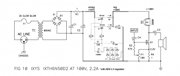
hello Mr.Pass,
i am interested to build de-lite with IXTH6N50D2 at 100vdc 2.2A
however at the articles mr.pass said there is an improvements offered by
power supply filter and regulator circuits as shown in Zen Variations #3
which will reduce noise and add more stability.
is this how we connect altogether? 🙄
and also for C1 and C2 how about if using 2x 47uf/250v like tube amp does, will it deliver more speed?
Happy New Year all...
Attachments
Last edited:
- Status
- Not open for further replies.
- Home
- General Interest
- diyAudio.com Articles
- De-Lite Amplifier