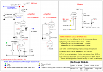
As you might have read, I am working on designing and building a tape head tube amplifier. For this you need quite some overall gain to overcome the gain losses in the equalization filter. Like at least 200.000; reason to split it up in 3 stages. Now every stage must have following specifications to make this work (with equalization filter in between)
Gain of minimum 60x per stage (I want triodes for linear behavior)
High input impedance > 1MOhm (the filter likes little load)
Low output impedance < 1kOhm (the filter likes low source impedance)
An output of at least 10V RMS with low THD (<1%) (your ears like this)
Low noise and hum (of course…)
Bandwidth of > 50kHz (not easy with triode/high-gain/no feedback)
There are only few triode tubes who will provide such high gains. The likes of ECC83, 6SL6, WE420A and 5755 are the most common ones. I used all of them in my Phonodude designs with excellent audio performance. The downside (as there always is one) from these tubes is the typical high plate resistance. But more on this later
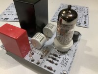
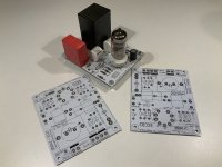
Certainly a proven and excellent way to achieve the above design criteria is the MU Follower. And then I had this idea of making it modular… just design a small PCB with one follower on it, which can be universally used. I already mentioned the tape head amplifier where you need three, but with two modules you could make a RIAA Phono amplifier with a passive RIAA filter between modules or just use one module as a pre amplifier? Of course that is for ONE Channel only….
the whole story is here: link to my blog site
Specially the influence of Ck (Decoupling the cathode resistor) in the Mu Follower was an eye opening and interesting aspect.
Never realized it would make sense to decouple with as little as 100nF ....
.
Gain of minimum 60x per stage (I want triodes for linear behavior)
High input impedance > 1MOhm (the filter likes little load)
Low output impedance < 1kOhm (the filter likes low source impedance)
An output of at least 10V RMS with low THD (<1%) (your ears like this)
Low noise and hum (of course…)
Bandwidth of > 50kHz (not easy with triode/high-gain/no feedback)
There are only few triode tubes who will provide such high gains. The likes of ECC83, 6SL6, WE420A and 5755 are the most common ones. I used all of them in my Phonodude designs with excellent audio performance. The downside (as there always is one) from these tubes is the typical high plate resistance. But more on this later
Certainly a proven and excellent way to achieve the above design criteria is the MU Follower. And then I had this idea of making it modular… just design a small PCB with one follower on it, which can be universally used. I already mentioned the tape head amplifier where you need three, but with two modules you could make a RIAA Phono amplifier with a passive RIAA filter between modules or just use one module as a pre amplifier? Of course that is for ONE Channel only….
the whole story is here: link to my blog site
Specially the influence of Ck (Decoupling the cathode resistor) in the Mu Follower was an eye opening and interesting aspect.
Never realized it would make sense to decouple with as little as 100nF ....
.
Attachments
Last edited: