Do you have drive reaching the input to the IC?
Not sure what you are asking? I am not sending any audio at the moment if that is the question.
Should I? Does it take some audio to turn on the drive wave?
If the amp won't oscillate, it could be that it requires a bit of signal to get it started, then it will oscillate at normal operating frequency (assuming that the circuit is complete, outputs in the amp, etc). If it still refuses to oscillate or if the amp circuit is incomplete, the input will allow you to test some parts of the circuit.
It's generally best to confirm that you have good drive to the outputs before you install them. The exception is for amps that will produce drive with no rail voltage. Then you remove the rectifiers.
I'd suggest that you remove the outputs and get signal to them before testing with the outputs in the circuit.
I'd suggest that you remove the outputs and get signal to them before testing with the outputs in the circuit.
I am driving a 60hz signal into the amp. I have the signal up to the driver card. from there i am not sure where it should be. I did replace all the ICs on the card.
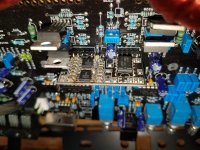
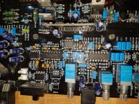
On pin 1 of the 2184 ic I have negative rail voltage using the the rail ground for my scope. I think i should see audio from pin 7 of IC 1 on the driver card which should go through the Q1 and Q2 then into the pin 1 of the 2184. I dont have a exact diagram of this card just a generic.
On pin 1 of the 2184 ic I have negative rail voltage using the the rail ground for my scope. I think i should see audio from pin 7 of IC 1 on the driver card which should go through the Q1 and Q2 then into the pin 1 of the 2184. I dont have a exact diagram of this card just a generic.
Attachments
Who drew the diagram?
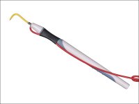
To probe the pins on the vertical board, make a probe with a dental probe or just make a temporary probe out of a piece of solid wire (salvaged from romex type wiring). Connect the wire to the probe with an alligator clip jumper.
You stated that you have signal out of pin 7. Is it the same frequency as the input signal or a higher frequency (80kHz)?
Is that signal getting to the base of Q1?
I think there may be an error in the Q1/2 part of the circuit.
Attachments
jacampb2 is the person that drew the diagram. I just copy it to my pc. You had made a reference to his post in another of my posts about a parts identify post.
you gave me this link:3S "mini" type driver clone
So was there a problem with my parts or the diagram?
you gave me this link:3S "mini" type driver clone
So was there a problem with my parts or the diagram?
- Status
- This old topic is closed. If you want to reopen this topic, contact a moderator using the "Report Post" button.
- Home
- General Interest
- Car Audio
- DD Z2B Stuck in protect