Did you confirm that there was drive up to the IC input before installing the IC?
Without the IC, do you see a triangle waveform on any of the op-amp IC outputs on that board?
Without the IC, do you see a triangle waveform on any of the op-amp IC outputs on that board?
do i need to drive a signal into it? where should i ground my scope? its not connected to the main ground on my power supply.
For most of the measurements, you can use either the primary or secondary ground. For measuring anything on the 2184, you should place the ground probe on the negative rail.
That was for a battery powered scope or multimeter. You cannot ground a mains powered scope to any supply voltage. To view waveforms with the negative rail as the reference with mains powered scopes, you need to use the scope in differential mode.
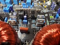
I don't have anything on this specific board. Boards with a similar layout of the two op-amps have a triangle waveform on pin 1 of the bottom op-amp. I was hoping that you had the same here.
Do you have 12v on the supply pin of the 2184?
That was for a battery powered scope or multimeter. You cannot ground a mains powered scope to any supply voltage. To view waveforms with the negative rail as the reference with mains powered scopes, you need to use the scope in differential mode.
I don't have anything on this specific board. Boards with a similar layout of the two op-amps have a triangle waveform on pin 1 of the bottom op-amp. I was hoping that you had the same here.
Do you have 12v on the supply pin of the 2184?
Do you see a spike of DC on the output filter inductors (before the relay) when you power the amp on (IC in the socket)?
- Home
- General Interest
- Car Audio
- DD Z2B help