Looking at my motors stash ready to start playing with the backlog of DD projects and thinking I ought to have a late model pancake motor for experimentation. I have one, from a JVC, but it's 2 phase and run with a FDD controller. Trying to find out if anyone made 3 phase pancakes (coils glued onto PCB style) in the 70s or 80s that found their way into anything affordable? So far my limited searching suggests most of the pancakes were in fact 2 phase.
Why? a pancake motor?
Hunt around in RC aircraft Motors. Very sophisticated motors of surprisingly good precision... really cheap too at from 10$ to 200$ (if nuts)
Wayyy better machinery, by My observations than those foisted onto Audio gear .
Add in a decent Electronic speed control: 10/20$ and a suitable Battery and you can dial in rpm feed back precision TT makers barely even dreamed about.
Audio is technology's forgotten stepchild these days.
Look elsewhere for genuine surprise
Yeah right. An RC heli motor will turn a platter directly. I did say DD. Given a cooking technics from 30 years go was quartz locked I assume you though I was talking about the all over the shop motors in cheap belt drives?
I want to test a theory/myth. the myth is that iron cored motors (such as used in the SL-1200) 'cog' and coreless motors (pancakes) don't and maybe mess with some 21st century contol schemes for BLDC. All for lolz, no sonic improvments expected
I want to test a theory/myth. the myth is that iron cored motors (such as used in the SL-1200) 'cog' and coreless motors (pancakes) don't and maybe mess with some 21st century contol schemes for BLDC. All for lolz, no sonic improvments expected
I can show you a graph of 1210 motor speed per revolution as. 360 degree chart. The number of motor poles are blatantly obvious.
Cordless motors still cog, just more gradually, more like a shaded pole ac unit.
Cordless motors still cog, just more gradually, more like a shaded pole ac unit.
I would be interested as the plots from the pink fish thread on that have vanished when I looked for them a couple of days ago. Step one is to replicate those. Step two is to see if newfangled drive methods actually make any difference
Coreless motors don't have any inherent cogging, but for constant torque you need enough phases and large enough field poles so that you can switch phases through constant gap flux. That is, for simple "hard" switching.
Think of it as a bunch of underhung speaker coils.
Think of it as a bunch of underhung speaker coils.
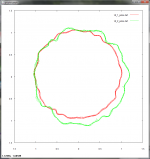
Bill, you're right they've all gone, i kept my own, but not the 1210 ones. Anyway, you could blatantly see the poles as a series of flat spots on the circle. it was almost an octogon.
You could, I just never printed it to analyse what the magnitude was or check if this was visible as FM across the band. I'll check some of George's measurements to see if he has any evidence from his tests.
I was shocked to read many years ago that the 1200 used square-wave drive - I assumed all DDs drove their motors with nice, low-distortion sine waves.Coreless motors don't have any inherent cogging, but for constant torque you need enough phases and large enough field poles so that you can switch phases through constant gap flux. That is, for simple "hard" switching.
Think of it as a bunch of underhung speaker coils.
Sine waves would surely be a large improvement, but even sines likely won't give absolutely constant torque, due to the nonlinearity of the magnetic field vs. distance (something like inverse square or inverse cube). It should be possible to measure the torque an energized coil makes vs. the angle of the platter pole piece to the coil, and do an inverse function to generate "true" constant torque.
Bill, you're right they've all gone, i kept my own, but not the 1210 ones. Anyway, you could blatantly see the poles as a series of flat spots on the circle. it was almost an octogon.
I saved the big pinkfish thread a few years ago when I saw it mentioned on diyaudio, if you can give me post numbers, I can likely find and post the plots, maybe even find some of the .wav files posted there.
I wrote some code to read frequencies in a .wav and output data for gnuplot, which is apparently exactly what the person in that other thread did.
I'll hunt for a look for the post numbers. It was the ones where there was a 'gear' shaped plot from the DD turntable.
The new kid on the block for DD drive is '180 degree commutation' which basically forces a current sine wave through the motor. When I say new kid, seems to be last 10 years. There is also some stuff on actually measuring the flux in real time, although that is more directed to removing the need for hall sensors by using DSP, so suspect its sub-optimal, but worth testing.
what I have found out in research this week is that the slot/pole ratio on many of the classic 70s/80s motors is not ideal and a fractional ratio is best. The japanese did know about this and a few of the top line megatables had this, but the rest of the range didn't. Does open up a really daft angle on rolling your own rotors...
Well looked throught that entire pinkfish thread and finally found it. The one of interest is post 247 which is an SL-1200. I might ping Lucky and see if he has anything saved as well.
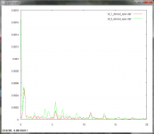
Here's what I found.


Now I'm looking at these plots again (not just in this post, but generally), they (again) bring up lots of questions.
With these two in particular, it appears that the LP may have been slightly off center on one of the TTs, causing the paths to be off center in relation to each other. One trace is on average larger in diameter than the other, indicating the platter speed is slightly higher. Having zero axes for x and y and a unit circle plotted would help show what's going on.
Both traces do have a consistent path for several revolutions, and I wonder if one is rotated if they could be matched closely, indicating the variations being recorded on the LP, as speculated in #248, or if these correspond to warps and bumps on the LP, frequency-modulating the recording as the stylus rides up and down.
Thanks. Like you I have questions from it. Green is the SL-1200, but I don't think the resolution of the test record is good enough. I'm tempted to try logging the FG signal directly and see what that gives to try and isolate motor from everything else.
Anyone got ideas for a cheap universal optical tacho with 1-2 degree marks? Would have been easy in the days when every office had a decent plotter in it. Shaft encoders commercially available are a bit OTT for what we need.
Unless the strobe markings on DD platters could be used...
Anyone got ideas for a cheap universal optical tacho with 1-2 degree marks? Would have been easy in the days when every office had a decent plotter in it. Shaft encoders commercially available are a bit OTT for what we need.
Unless the strobe markings on DD platters could be used...
http://www.vishay.com/docs/83760/tcrt5000.pdf
'might' work on the platter strobe markings. Spec sheet doesn't really give useful info on minimum feature size though. Will order one up to see.
'might' work on the platter strobe markings. Spec sheet doesn't really give useful info on minimum feature size though. Will order one up to see.
Hi, the two phase pancake motors using the SM6415 AS-4, which includes teac, jvc, oynkyo models (even the micro seiki dqx 1000 and luxman PD441/4's.) Their FG's put out a ~6mv sine at 50Hz at 33 1/3 and 67.5Hz at 45rpm.
https://www.flickr.com/photos/59684834@N08/26657205396/
Here's a 24v rega motor running in silicon oil to compare to the 1210...
Here's a 24v rega motor running in silicon oil to compare to the 1210...
I'm afraid not. It'll be pretty tight, it's very circular, grossly speaking and the 16 ridges you can see per revolution which relate to the motor poles are very well suppressed.
I'd imagine very tight sidebands +/-30hz from the test tone and right down in level. That's pretty much as good as I've seen from a single Ac motor.
I'd love to see one from Pyramid's PSU and Tacho.
I'd imagine very tight sidebands +/-30hz from the test tone and right down in level. That's pretty much as good as I've seen from a single Ac motor.
I'd love to see one from Pyramid's PSU and Tacho.
- Status
- Not open for further replies.
- Home
- Source & Line
- Analogue Source
- DD pancake motors