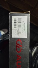
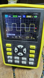
Hello friends, greeting you again. I am trying to repair another DD DM1000A that came into my hands. This time the amplifier arrived with damaged IC irs2092s, the entire output stage was removed to check output mosfets and necessary voltages in the IC, only the IC was changed and it began to pulsate. Now the problem is that the output fets which are Irfb52n15d get too hot and there is a working frequency of 345khz, I don't know if the frequency is high, I checked resistors near the IC and everything is fine, I have audio at the output and a current consumption of 1.75 amps, what else can I do to prevent the output mosfets from getting so hot?
Attachments

That seems high for a subwoofer amplifier. Can you post a closeup of the components on/near pins 1-8 of the IC?
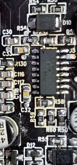
I can't tell from the photo (black board) but the oscillation frequency is determined by the value of C1, C2 and R1 on page 3 of the attached AN. You may not be able to tell the value of the capacitors but what is the value of the equivalent of R1 in the application note?
Attachments
Are the Irfb52n15d the original FETs that were in this amp?
Isn't this a subwoofer only amplifier (not a full range amplifier)?
It's sometimes difficult to measure the carrier frequency when amplifiers are being driven hard but can you see if the oscillation frequency drops significantly when driven hard?
Isn't this a subwoofer only amplifier (not a full range amplifier)?
It's sometimes difficult to measure the carrier frequency when amplifiers are being driven hard but can you see if the oscillation frequency drops significantly when driven hard?
I once had a fault just like yours on 2 x DM1000. I found the buffer transistors were faulty, causing the output fets to get hot. So, check those transistors. If memory is correct, those transistors are just below the output fets.
I also had another Dm1000 also with output fets getting hot, and then the amp should go into protection. What I found was that the power supply frequency was too high. With this fault, I found a cap on PIn 4 of the 494 that was broken. Changed that, and amp worked fine
I also had another Dm1000 also with output fets getting hot, and then the amp should go into protection. What I found was that the power supply frequency was too high. With this fault, I found a cap on PIn 4 of the 494 that was broken. Changed that, and amp worked fine
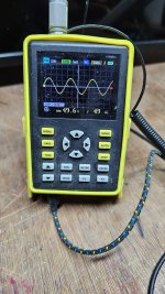
Hi friends, back today with some results. I've managed to make them run cooler and consume less current. Now, when I play music at its limit, the IRS2092s stops pulsing until I lower the gain and it starts working again. How can I avoid this? I've included two photos showing the output at its limit and the operating frequency at the source.
Attachments
Is it still operating at 345kHz?
What FETs did you use?
If you drive it to clipping, no load, does it shut down?
What FETs did you use?
If you drive it to clipping, no load, does it shut down?
It's still working at 345 kHz, it's working with a new batch of Irfb52n15d and new D310 and D301, the D300 was leaking. I still changed both. I set it to clipping and it doesn't turn off, but when I play normal music it turns off.
Recheck those. Pin 7 is supposed to be a 5.1v reference.
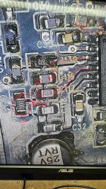
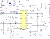
There are 4 resistors circled in the attached diagram. Your will be different except for the connections to the IC. I need to know their values and confirm that they're soldered properly to their pads.
There are 4 resistors circled in the attached diagram. Your will be different except for the connections to the IC. I need to know their values and confirm that they're soldered properly to their pads.
Attachments
pin 7 R58 1.8 kohms within the value
Pin 8 R59 39 kohms within the value
Pin 16 R51 5.6 kohms within the value
Pin 8 R59 39 kohms within the value
Pin 16 R51 5.6 kohms within the value
I couldn't find R43 in the drawing or it seems that it doesn't exist, only the 5.6k one and this one had false terminals and has already been replaced, even though pins 7 and 8 have the same voltages.
The CSD can be driven from an external source or from within the IC. Is there a diode or some other component connected to pin 5, other than the CSD capacitor?
- Home
- General Interest
- Car Audio
- DD DM1000A Excessive heating on output FETs