I've got this issue with the HF section of one DCX464 being almost 5.5 dB less sensitive at some frequencies than a second unit. I'm hoping anyone has something to say about how this is possible with such costly units. Could it be that the build spread is this big? I very much would like to doubt that!
A bit of background:
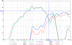
I've been working on a synergy horn using the B&C DCX464-16 and Faital Pro 12H500. The horns are finished and pretty well constructed with only minimal differences. But when measuring the two DCX units this afternoon, the HF of one was almost 5.5 dB down compared to the HF of other unit at 3.6 kHz 😕😕.
No settings were changed in between, as can be seen from the mids respons of the two units, which is pretty identical. I have tried covering the woofer entries with solid plywood, but it made no difference.
A thought that came to mind was, maybe they had accidentally put in an 8 Ohm HF membrane instead of a 16 Ohm version, but that would result in similar frequency respons curve, right? Just to be sure, I measured the DC resistance, which turned out to be 8.3 Ohms on both units...
I removed the "faulty" HF unit to check if there might be an issue with the membrane, but it seemed fine.
I'm at a loss here and my next step will be to contact the distributor (toutlehauteparleur in France) to apply for an rma.
I thought maybe Bennett Prescott would have some insights?
I was about to start designing a passive crossover for the horns, but this frequency difference makes it really difficult. What will happen if an HF gets blown and gets replaced? There's no way to design for this big differences in SPL🙁.
Update:
For the solution, see post #13.
A bit of background:
I've been working on a synergy horn using the B&C DCX464-16 and Faital Pro 12H500. The horns are finished and pretty well constructed with only minimal differences. But when measuring the two DCX units this afternoon, the HF of one was almost 5.5 dB down compared to the HF of other unit at 3.6 kHz 😕😕.
No settings were changed in between, as can be seen from the mids respons of the two units, which is pretty identical. I have tried covering the woofer entries with solid plywood, but it made no difference.
A thought that came to mind was, maybe they had accidentally put in an 8 Ohm HF membrane instead of a 16 Ohm version, but that would result in similar frequency respons curve, right? Just to be sure, I measured the DC resistance, which turned out to be 8.3 Ohms on both units...
I removed the "faulty" HF unit to check if there might be an issue with the membrane, but it seemed fine.
I'm at a loss here and my next step will be to contact the distributor (toutlehauteparleur in France) to apply for an rma.
I thought maybe Bennett Prescott would have some insights?
I was about to start designing a passive crossover for the horns, but this frequency difference makes it really difficult. What will happen if an HF gets blown and gets replaced? There's no way to design for this big differences in SPL🙁.
Update:
For the solution, see post #13.
Attachments


Last edited:
Hi, That's way too much variance i think.
I only have one dcx464, or i'd do a quick compare for you.
I have compared 4 of the bms4594he's and i consider them substitutes for each other.
The B&C should be the same way for sure.
Your two comparisons are on the same synergy horn, yes?
And no chance of a drive level mistake?
Pls pardon those questions...but i often find myself making user errors..
Hi!Could it be that the build spread is this big? I very much would like to doubt that!
Definetly build spread must not be this big 🙁
My pair https://www.diyaudio.com/forums/attachments/multi-way/782660d1569100887-dcx464-untitled-2-png
They are not on the same synergy horn, although the horns are identical up to the millimeter. I also closed the woofer entry points, but that didn't change the HF response at all.
No settings were changed in between. Just changed the cab and hooked up the cables again, followed by a repeat of the REW measurement-no change in settings whatsoever. I measured mid and high section of both drivers several times with identical results. The response of the mid sections is near identical, proving nothing has changed in the settings.
I can't believe that the mids would be so identical when something would be off with the horns, while the HF responses are so different.
@Flaesh: that looks like identical units indeed! That's what I expected.
Alright, time to contact the distributor🙁
Even tough the horns measure the same I would swap the drivers and re measure. Just to rule everything else out.
Regards
Charles
Regards
Charles
could try swapping the diaphragms from one to the other and see if it follows. easier than removing the drivers anyways.
Thijs666,I've got this issue with the HF section of one DCX464 being almost 5.5 dB less sensitive at some frequencies than a second unit. I'm hoping anyone has something to say about how this is possible with such costly units.
No settings were changed in between, as can be seen from the mids respons of the two units, which is pretty identical.
I was about to start designing a passive crossover for the horns, but this frequency difference makes it really difficult.
Although what you measured could be unit to unit variation, I suspect the clip lead/bare wire used may have introduced a different series resistance between the two tests, coupling with the varying impedance of the horn/driver a high resistance connection would change the frequency response. A DC resistance test measurement on the diaphragm by itself would not duplicate the measurement cable/clip lead resistance.
Using clip leads swapping components while prototyping crossovers, too many times measured a response near "perfect", only to find a very different response switching back to the same components. It is truly amazing how much series resistance can vary on what looks like a perfectly good connection, and how much time can be wasted if it's not ;^).
Try another test with the mic between the two horns, swap driver connections and see if they still sound/look different.
Good luck!
Art
No, it wasn't. But it looked like that would be a really invasive procedure, so I didn't want to risk the warranty.i know the diaphragm was visually inspected but was it removed and the gap checked?
could try swapping the diaphragms from one to the other and see if it follows. easier than removing the drivers anyways.
That's a good tip. Thanks 😉
Hi Art,Thijs666,
Although what you measured could be unit to unit variation, I suspect the clip lead/bare wire used may have introduced a different series resistance between the two tests, coupling with the varying impedance of the horn/driver a high resistance connection would change the frequency response. A DC resistance test measurement on the diaphragm by itself would not duplicate the measurement cable/clip lead resistance.
Using clip leads swapping components while prototyping crossovers, too many times measured a response near "perfect", only to find a very different response switching back to the same components. It is truly amazing how much series resistance can vary on what looks like a perfectly good connection, and how much time can be wasted if it's not ;^).
Try another test with the mic between the two horns, swap driver connections and see if they still sound/look different.
Good luck!
Art
Thanks for your reply! Sadly I know from experience how bad alligator clips can be, so that's the first thing I tried to rule out by clamping, re-clamping and remeasuring and inbetween switching to the midrange driver (and verifying its frequency response was still identical to that of the other unit) and back a multiple times, but ALL measurements were consistent, so I very much doubt it was added series resistance due to a bad connection.
(Also, wouldn't a series resistance add resistance evenly throughout the frequency range?)
Luckily I wasn't prototyping with crossovers yet, I just started doing measurements of the bare drivers in-horn, so I could have a go with XSIM 😉.
The speakers aren't at my location, but I'm heading over again tomorrow. I didn't do an impedance plot of the "bad" driver yet, but I'm curious how it compares, so I'll do that tomorrow, together with the suggestions here and report back. I hope to sort it out and that it's just an error from my side😱
Clip lead series resistance could change in a single measurement, for example starting at a high resistance, then lowering as current goes through the circuit over time. In a low-to-high sweep, this could result in more attenuation in the lower portion of the sweep, similar to your posted result.Sadly I know from experience how bad alligator clips can be, so that's the first thing I tried to rule out by clamping, re-clamping and remeasuring and inbetween switching to the midrange driver (and verifying its frequency response was still identical to that of the other unit) and back a multiple times, but ALL measurements were consistent, so I very much doubt it was added series resistance due to a bad connection.
(Also, wouldn't a series resistance add resistance evenly throughout the frequency range?)
That said, I missed that you had written in post #4 that you had measured mid and high section of both drivers several times with identical results, which would rule out variable clip lead resistance as the problem source, as the measurements would not be consistent.
Update!
We've received a replacement diaphragm and while replacing the old one, I noticed some sticky stuff holding the old coil in a bit. It wasn't strong glue, but there was definitely something on the inside of the voice coil and inside the magnetic gap that wasn't supposed to be there. It was like a 1 inch long smear of something sticky. I cleaned up the magnetic gap as well as I could until the new diaphragm didn't stick inside the gap anymore and put everything together again.
The measurements we did afterwards verified that this had resolved the issue and that the frequency curve now is exactly identical to the other unit's curve.
Just so you know 😉.
Last edited:
- Home
- Loudspeakers
- Multi-Way
- DCX464 busted? >5dB difference in HF