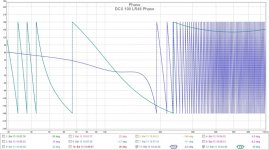
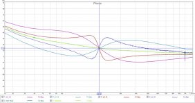
So everybody is saying that DCX has the same phase response as analog filter. Well I measured it and it is simply not true - take a look at the pictures.
HP filter does seem to act somewhat "textbooky" but the LP does not, it seems to be far more linear at the crossover frequency. I've tested this in various configurations and this tendency does not depend on frequency (100Hz and 1Hz illustrated) or filter type (LR48 shown for more clarity).
Anyone got an explanation for this and perhaps a way to overcome or compensate for this strange phase behavior?
Attachments

Your measurement scheme is incorrect. You need to discount the latency of the unit when evaluating phase response.
The easiest way to view phase response is to use one output channel of the DCX with zero programming applied as your reference channel and then measure relative to that with your other channel in a differential scheme.
I guarantee you'll then see phase response identical to an analog equivalent filter.
Cheers,
Dave.
Last edited:
WXN,I agree with the above. I've done DCX measurements using HOLMImpulse and the transfer functions were pretty much textbook. Take a look at latency. HOLMImpulse can manage that for you, if you don't have another way to do it.
WXN-
Since you are measuring the DCX can you do me a favor and measure some EQ bands with a couple values of Q and equal amounts of boost and cut dB?
For instance, can you measure EQ centered on 1000Hz (any frequency is OK, but keep it constant) for:
Q=1 gain = +6dB
Q=1 gain = -6dB
Q=4 gain = +6dB
Q=4 gain = -6dB
Also, can you measure the output with two bands on the same channel that have the same Fo, Q, and gain magnitude but have +gain and -gain, like this:
EQ1: Fo=1kHz, Q=1, -6dB
EQ1: Fo=1kHz, Q=1, +6dB
measure the output = EQ1 + EQ2
I want to see if the bands cancel and the output is "flat" (or not).
Can you post the results here?
If anyone else can do it, or knows the behavior of the EQ bands for the DCX, please post. Thanks,
-Charlie
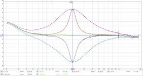
Here are the graphs, no smoothing. Please ignore the wiggly baseline, it's caused by the aging EQ in my mixer.
The EQ1+EQ2 curve does seem to be pretty much identical to the baseline.
There is a peak at 1kHz and its harmonics present in all of these curves, not sure about its origins.
The EQ1+EQ2 curve does seem to be pretty much identical to the baseline.
There is a peak at 1kHz and its harmonics present in all of these curves, not sure about its origins.
Attachments
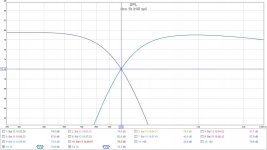
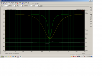
Charlie is asking for the "definition of bandwidth" for the Q settings of the DCX2496. Here's a measurement of Q=1 and Q=4 for a 1khz notch filter -6db. (The +6db measurements are exactly opposite of these as expected.)
The second measurement you asked for yields a perfectly flat response.......as expected.
Cheers,
Dave.
The second measurement you asked for yields a perfectly flat response.......as expected.
Cheers,
Dave.
Attachments
Charlie is asking for the "definition of bandwidth" for the Q settings of the DCX2496. Here's a measurement of Q=1 and Q=4 for a 1khz notch filter -6db. (The +6db measurements are exactly opposite of these as expected.)
The second measurement you asked for yields a perfectly flat response.......as expected.
Cheers,
Dave.
Dave - thanks for posting that. I've been able to check this against a new version of the Active Crossover Designer that I have been working up.
These EQ bands are "symmetrical", which is not the same as what you get when you design an analog EQ stage (one with negative gain at least).
The phase looks right to me (in response to O/P).
-Charlie
Last edited:
Not to be picky but what exactly did I do wrong this time? It's exactly the same, except for different scale...
Not to be picky but what exactly did I do wrong this time? It's exactly the same, except for different scale...
You didn't do anything wrong... Dave just posted a very clear plot without the funny skew. I needed to read off some values to compare with some of my own results and his plot worked well for me for that purpose.
Thanks for checking that the bands cancel. I needed to have that confirmed.
Cheers,
-Charlie
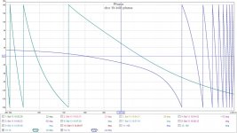
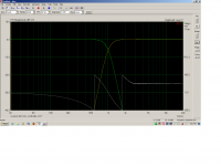
For reference: Here's what the phase response of an LR48 filter at 1khz programmed on my DCX2496 looks like. Note the phase "wraps" twice and it's 0 degrees at 1khz.
I was measuring the low-pass filter only here, so the phase response above about 3khz is not correct since signal level was so low.
Hope that helps.
Dave.
I was measuring the low-pass filter only here, so the phase response above about 3khz is not correct since signal level was so low.
Hope that helps.
Dave.
Attachments
I have to ask, have you checked the filter various filters and found them all to be accurate on the DCX?
Have you noticed anything that is not accurate (versus the analog equivalent) on the unit in terms of amplitude and phase characteristics?
-Charlie
Have you noticed anything that is not accurate (versus the analog equivalent) on the unit in terms of amplitude and phase characteristics?
-Charlie
I've checked many of the filter settings and found all to be accurate.
As you're probably aware, the bandwidth of the notch filters and the "Q" setting that corresponds to a particular bandwidth can vary on many of the DSP crossover boxes.
The "phase" control portion of the DCX is somewhat interesting and might not be understood by some users.
All in all, the DCX has the most intuitive configuration setup and adjustment scheme of any of the DSP boxes I've used. This only applies to the GUI control via serial link though. Operating the unit from the front panel controls can be quite tedious. 🙂
Cheers,
Dave.
I've never used the GUI via RS232...
What's the phase control that you mentioned above.
I should add that I haven't used a DCX in quite awhile now!
-Charlie
What's the phase control that you mentioned above.
I should add that I haven't used a DCX in quite awhile now!
-Charlie
The GUI is very easy to use. But I'm so used to the front panel that I don't even bother with the GUI any more. 🙂
What's the phase control that you mentioned above.
-Charlie
The phase control induces a second-order all-pass function. It monitors the LP filter frequency setting in the crossover configuration (whether you have the crossover active or not) and shifts phase at this frequency per the degree setting you select on the "short delay" tab.
So, as an example, if the LP filter setting is at 1khz and you adjust the phase control to 180 degrees in that channel, you'll see a 0 to 360 degree phase shift across the audio band with the phase "wrapping" through 180 degrees at 1khz.
Biquad coefficients (48khz) for an equivalent would look like this:
b0= 0.877223696015605
b1= -1.873204415984120
b2= 1.000000000000000
a1= 1.873204415984120
a2= -0.877223696015605
Cheers,
Dave.
Last edited:
- Status
- Not open for further replies.
- Home
- Source & Line
- Digital Line Level
- DCX2496 XO phase response oddities