Better get the type of inverter that gives mains off batteries, used for converting solar or stored energy.
Such as UPS for computers and so on.
From line AC thus generated, convert down using a normal SMPS.
That is easier.
You might find such units being commonly used in motor homes for example.
Such as UPS for computers and so on.
From line AC thus generated, convert down using a normal SMPS.
That is easier.
You might find such units being commonly used in motor homes for example.
I am connecting a 0-10V analog output (+/-.0005v) from a Galil motion controller to a cheap 0-100v digital read
Going right back to the start... what is the meter you are using? and can it be altered easily such that (say) 0 to 1 volt or 0 to 10 volt displays as 0 to 100. No normal digital meter will take a raw 100v and display that, it will be attenuated somewhere, just like an old multimeter that might use a 50uA meter movement for all ranges.
Are we making this all to complicated when there might be a simpler solution.
LT8634 is "overkill", but there is a development board DC2716A (will have to change the caps to slightly higher values). It's $91 at Arrow. Datasheets are on ADI's website. Again, I don't know how "noisy" it will be so a post-regulator may be needed.
Neat circuit 👍 although we still need a low voltage neg rail as well. I'd bet you could get that from the circuit with a bit of creativity... a few caps and a couple diodes from the switching side of it.
Noise on the rails within reason wouldn't be a problem for an opamp.
Don't fully understand the graph, looks like a (non-linear) response curve to an applied voltage. Response time is on human scale, the readout is to display mechanically rotated trunnion feedback to operator. So maybe 100ms response is adequate. My first thought was to use an audio amp chip, or even a cheap mono amp at a set gain. But amps take mV input (phono, cd, etc.). So an amp chip that could take 10v input is the ticket. Does the Cockroft-Walton voltage multiplier need regulation to handle transient functionality? How is the power supply the stumbling block? What size caps would I need? 5 stages would give me 5x gain (minus diode drops) correct?
So that would be a square wave signal +-10V referenced to ground that can be used as supply?My supply signal is a transconductance 60khz servo motor drive putting out +/-10V (max) with peak 10A
(be sure it doesn´t put out any nasty voltage spikes!)
Then two diodes and two capacitors could make that a +-10VDC supply. (see upper circuit)
The positive +10V could be boosted to 45-50V with one of these super cheap XL6009 PCBs that can be had at several sources.
(they do 3A and are over the top for this application but you won´t find anything else as cheap as that)
With some extra effort you could still use a villard cascade instead of those XL6009 but at the price of lots of experimenting, extra filtering and a probably larger circuit than the tiny XL6009-PCB. (see 2nd circuit; the V+ at bottom right is ~58V, don´t know why that automatic label doesn´t work there)
Then you still need to build Mooly´s circuit from post 11 and buy an (maybe not so cheap) opamp that can handle this +50V/-10V power supply.
All together quite an effort. I´d still look at modifying or exchanging that digital meter.
Attachments

Last edited:
That's a transient graph, it illustrates the 3 milliseconds it takes for the LT8634 to achieve +50V. The capacitors on the development board are rated 50V and are size 0402, so they would need upgrading to 100V.Don't fully understand the graph, looks like a (non-linear) response curve to an applied voltage. Response time is on human scale, the readout is to display mechanically rotated trunnion feedback to operator. So maybe 100ms response is adequate. My first thought was to use an audio amp chip, or even a cheap mono amp at a set gain. But amps take mV input (phono, cd, etc.). So an amp chip that could take 10v input is the ticket. Does the Cockroft-Walton voltage multiplier need regulation to handle transient functionality? How is the power supply the stumbling block? What size caps would I need? 5 stages would give me 5x gain (minus diode drops) correct?
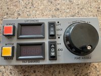
I will soak on the above. I can supply 24vdc (the ps that powers the controller), I can provide variable 0-10v (signal) or 0-10v(pwm 60khz) signal (from the controller). The volt meter is locked in (see control panel). Looking at the digital readout, do you think some of these SM components could be swapped to make 10v read 100.0v? (the actual readout has 2 decimal places). Also, can I take one of those cheap boards and swap some resistors to get a 0-50v output range? Thanks.
Attachments

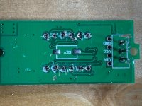
If you look at the PCB of the meter and look where the input voltage is applied can you see any form of voltage divider network (resistors).
The basic meter possibly reads 99.99 millivolts in raw form and will have a resistive network added to divide 99.99 volts down to 99.99 millivolts. Change the divider and you can make it read whatever you want for a given input.
The basic meter possibly reads 99.99 millivolts in raw form and will have a resistive network added to divide 99.99 volts down to 99.99 millivolts. Change the divider and you can make it read whatever you want for a given input.

Here's where I am at so far. Tracked some of the traces, and found the controller chip (quite powerful). Please help ID the specific resistors (R1 & R3 is my guess), and what the new values might be. Thanks.
Attachments
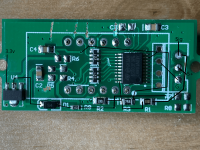
Have a look at this and see if it looks about right. I think R3 might be to provide some minute input signal, perhaps to prevent some 'dither' at zero volt input. It looks like a '755' which would be 7500000 or 7.5 meg.
The values don't give a 10 to 1 ratio but I suppose that could be corrected by the programming.
I think you are going to have to experiment a bit. If its not easy to work on then maybe bring some wires out from those points.
This is how it seems to work now:

If we set the input voltage to 10 volts and you reduce R1 we can get the same input to the convertor. So that means 10v in should read 100 on the meter.

R2 is now becoming significant as a 'load' in drawing current from the applied input voltage.
I think you are going to have to experiment a bit it does look as though playing with that resistor might achieve what you want... hopefully.
The values don't give a 10 to 1 ratio but I suppose that could be corrected by the programming.
I think you are going to have to experiment a bit. If its not easy to work on then maybe bring some wires out from those points.
This is how it seems to work now:
If we set the input voltage to 10 volts and you reduce R1 we can get the same input to the convertor. So that means 10v in should read 100 on the meter.
R2 is now becoming significant as a 'load' in drawing current from the applied input voltage.
I think you are going to have to experiment a bit it does look as though playing with that resistor might achieve what you want... hopefully.
Voltage across R2 is really the one I'm looking at as that is effectively the voltage applied to the chip. It seems to follow a reasonable kind of progression given that the meter loading will later things a little (and different meter ranges perhaps).
So 1v in for 0.095v out, 10v in for 0.912v out and 3.625 for 40v in.
I think what you need to do is tag a preset across the 100k (perhaps a multiturn ultimately) and adjust to suit. Something like a 2k2 preset. Begin with the preset at max resistance.
So 1v in for 0.095v out, 10v in for 0.912v out and 3.625 for 40v in.
I think what you need to do is tag a preset across the 100k (perhaps a multiturn ultimately) and adjust to suit. Something like a 2k2 preset. Begin with the preset at max resistance.
I assume the cross over on R3 at around 36.5v has something to do with this readout blinking out @34v. I ordered a different display. Will get it Thursday.
Possibly yes. There could be more going on than we can just see from the PCB images. These challenges are things you have to actually get experimental with which isn't always easy I know.
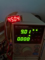
Got another display (0-100v 2 digit), patched in a 200k pot over the board 120k, adjusted to about 13k and Walla, 45.00 (deg) @9.00v. And it's linear to zero. Fantastic! Thanks all for the helping hand.
Now I have another idea and need a cheap (Arduino type) board that converts quadrature counts (not count rate) to volts. A cheap version of this: https://www.motrona.com/en/products...gnal-converter-incremental-analog-serial.html.
Now I have another idea and need a cheap (Arduino type) board that converts quadrature counts (not count rate) to volts. A cheap version of this: https://www.motrona.com/en/products...gnal-converter-incremental-analog-serial.html.
Attachments
- Home
- Amplifiers
- Power Supplies
- DC voltage multiplier for battery powered amp