Have a question regarding dc servo.
A. How do you calculate the corner frequency of the high pass filter formed by the DC servo?
B. What is the Q of the DC servo's HP filter function of?
C. How do you figure out the ratio of servo signal injection resistor and the main feedback resistor?
Art
A. How do you calculate the corner frequency of the high pass filter formed by the DC servo?
B. What is the Q of the DC servo's HP filter function of?
C. How do you figure out the ratio of servo signal injection resistor and the main feedback resistor?
Art
A DC servo is normally designed by first deciding what servo authority is required, i.e. the maximum correction the servo can provide or the worst case offset the servo alone can create if the opamp fails and swings to one rail.
If, for example the opamp rails are +/- 20V then if the servo injection resistor is 10x the main feedback resistor (the one connected to the amplifier output) the servo can at most correct an offset of 2V.
Now a -3dB point for the system is chosen. The integrator response will fall at 10dB per decade, so if a -3dB point of 0.1Hz is chosen then the integrator's unity gain frequency must be 1Hz (the gain will be 10 at 0.1Hz).
You can see an example of a non-inverting integrator with a unity gain frequency given by f=1/(2*pi()*R*C) here:- John Conover: Direct Coupled Stereo Headphone Amplifier
Remember that the injection resistor connects to an effective AC ground at one end and is therefore in parallel with the feedback network resistor which is connected to ground, and therefore affects the overall amplifier gain.
Check to see the point where the opamp will be driven into clipping if the amplifier rails are higher than the opamp rails and make sure the gain has fallen sufficiently while still below frequencies likely to be encountered.
Last edited:
That 10 dB/decade should be 20 dB/decade, otherwise I agree with everything counter culture wrote.
By replacing the input resistor of the integrator with a voltage divider you can make sure that the integrator op-amp will never be driven out of its input voltage range. The procedure is as follows:
-Calculate the resistor from amplifier output to op-amp positive input by the methods explained by counter culture
-Add a resistor from op-amp positive input to ground with a value that is just small enough to ensure the op-amp input will never be driven outside its specified common-mode voltage range
-The resistor from the op-amp negative input to ground now has to have a value equal to that of the parallel connection of the two resistors at the positive op-amp input
The only disadvantages are that you need an extra resistor and that there is some amplification from op-amp offset to amplifier output offset. For example, if the voltage divider divides by four, the output offset will be four times the op-amp offset.
Yes, of course, I apologise for this slip, it should of course read 'integrator response will fall at 20dB per decade'.
Have a question regarding dc servo.
C. How do you figure out the ratio of servo signal injection resistor and the main feedback resistor? Art
Hi Art,
There are a few designers of symmetrical input amps that believe adjusting the current sources to null the DC offset gives better sonics than summing the servo voltage with one of the inputs. From my experience, the range of control is smaller with this current control than the normal voltage summation control, so component matching is necessary as might be done with DIY and not volume production products.
I will confess to believing I heard a difference on the Gilmore Headphone amp.... more dynamic transients when the servo voltage does not sum with the feedback path. A very easy experiment for symmetrical input designs. Using headphones was helpful to my ears.
Attachments
Hi Art,
There are a few designers of symmetrical input amps that believe adjusting the current sources to null the DC offset gives better sonics than summing the servo voltage with one of the inputs. From my experience, the range of control is smaller with this current control than the normal voltage summation control, so component matching is necessary as might be done with DIY and not volume production products.
I will confess to believing I heard a difference on the Gilmore Headphone amp.... more dynamic transients when the servo voltage does not sum with the feedback path. A very easy experiment for symmetrical input designs. Using headphones was helpful to my ears.
How do you design this? Don't you need to know the sign of the offset of the NPN and PNP differential pairs to predict the sign of the loop gain of this loop? Or do you just use one branch of the differential pairs and therefore have a predictable transfer from tail current to current injected in the signal path (namely half the tail current)?
How do you design this? Don't you need to know the sign of the offset of the NPN and PNP differential pairs to predict the sign of the loop gain of this loop? Or do you just use one branch of the differential pairs and therefore have a predictable transfer from tail current to current injected in the signal path (namely half the tail current)?
Hi Marcel,
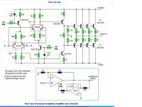
I attached two examples of complementary symmetrical input amps: the Gilmore headphone amp, and Stephen's no-global-feedback amp.
As you can see, with a complementary symmetrical input the servo amp "pushes and pulls" or "increases and decreases" the currents sources to the two long tail input diff pairs. This generates DC bias current adjustments similar to summing a DC voltage proportional to the output DC offset until the output DC offset is nulled.
I believe any amp with a DC servo claiming to have "no global feedback" must use this type current-adjustment design.
I only have experience designing servos for complementary symmetrical input amps.
Attachments

Last edited:
In the Stephen Hawksford amplifier, are the resistors on top of the first stage of unequal value? If so, then I understand it.
In the other amplifier, you have the very non-linear voltage division between a resistor and an LED in the DC bias loop. Doesn't that affect the low-frequency distortion? Or can you dimension everything such that this always has a negligible effect on the distortion?
In the other amplifier, you have the very non-linear voltage division between a resistor and an LED in the DC bias loop. Doesn't that affect the low-frequency distortion? Or can you dimension everything such that this always has a negligible effect on the distortion?
go to
http://www.diyaudio.com/forums/chip-amps/107246-dc-servo-question.html#post1283350
If the answer is not in there I will be very surprised.
Use Gootee's simulation.
http://www.diyaudio.com/forums/chip-amps/107246-dc-servo-question.html#post1283350
If the answer is not in there I will be very surprised.
Use Gootee's simulation.
In the Stephen Hawksford amplifier, are the resistors on top of the first stage of unequal value? If so, then I understand it.
In the other amplifier, you have the very non-linear voltage division between a resistor and an LED in the DC bias loop. Doesn't that affect the low-frequency distortion? Or can you dimension everything such that this always has a negligible effect on the distortion?
Hi Marcel,
You are correct. In Stephen's no-global-feedback design the top resistors of the diff-amps are of unequal value, with the negative input side pullup being a smaller resistance to supply the VAS current.
In the Gilmore headphone amp, the resistor connecting the servo to the LED is made large enough to just pull/push the LED bias current by about 15%, and thus not affect the initial power-up of the current source.
I have used the Gilmore/LED design with good results, and measured no power-up or drift issues. The THD20Khz is just as low as with a traditional voltage summation servo. From my experience, the current adjust servos cannot provide as much DC offset adjustment and hence require well matched circuits.
If an LED were an ideal diode, a 15 % change in bias current would only change the voltage across the LED by (kT/q)*ln(1.15)~=0.15 kT/q~=4 mV. Because of non-idealities of the LED it may be a bit more, but I can imagine that the control range is rather limited.
Regarding distortion, if there are any problems you would see them at low audio frequencies rather than high audio frequencies. Is the THD at 20 Hz also good?
Regarding distortion, if there are any problems you would see them at low audio frequencies rather than high audio frequencies. Is the THD at 20 Hz also good?
If an LED were an ideal diode... I can imagine that the control range is rather limited.
Regarding distortion, if there are any problems you would see them at low audio frequencies rather than high audio frequencies. Is the THD at 20 Hz also good?
Marcel,
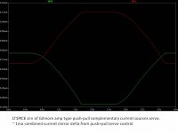
I attached a LTSpice sim of the Gilmore amp type complementary current sources with the DC servo attached to the LEDs for offset adjustment. The sim shows about +/- 0.5 ma on each for the 8.8ma nominal average.
For my DIY amps, I adjust the resistors on each current source pair to provide 0V DC offset after warmup, and only trust the DC servo to compensate for +/- 50mv DC input offset before shelf comparators open up the output relay.
The servo sims show only a minor affect on TH 20Hz since there is both an integrator capacitor on the servo opamp plus a large 100uF filter capacitor on each LED diode.
Attachments
- Status
- Not open for further replies.
- Home
- Amplifiers
- Solid State
- DC servo