Hi there,
we're planing to build some amplifiers based on the great concept "LPUHP" originally discussed here: The Wire - Low Power Ultra High Perfromance (LPUHP) 16W Power Amplifier
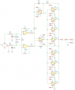
We plan to add a DC servo to the mix. I attached a schematic of what I have in mind and am looking forward to comments on it, especially if it's feasible to use the upper lead of R207 (normally connected to GND without the servo) to input the feedback signal from the DC servo.
Cheers, Jürgen
we're planing to build some amplifiers based on the great concept "LPUHP" originally discussed here: The Wire - Low Power Ultra High Perfromance (LPUHP) 16W Power Amplifier
We plan to add a DC servo to the mix. I attached a schematic of what I have in mind and am looking forward to comments on it, especially if it's feasible to use the upper lead of R207 (normally connected to GND without the servo) to input the feedback signal from the DC servo.
Cheers, Jürgen
Attachments
Last edited:
Hi there,
we're planing to build some amplifiers based on the great concept "LPUHP" originally discussed here: The Wire - Low Power Ultra High Perfromance (LPUHP) 16W Power Amplifier
We plan to add a DC servo to the mix. I attached a schematic of what I have in mind and am looking forward to comments on it, especially if it's feasible to use the upper lead of R207 (normally connected to GND without the servo) to input the feedback signal from the DC servo.
Cheers, Jürgen
IMO you should have low value resistor on every "output stage" opamp and take the feedback from the summing node. Also, you should experiment with "bw" pin of the LME diamond buffer, floating pin is 110MHz bandwidth, it's plenty enough... you should also experiment with listening and measurements on the proto. I guess the pcb board is critical too... Don't waste much time on simulation with this kond of topologies..
Last edited:
You mean a resistor in series with every buffer? To repeat, the LPUHP design is not by me and is already fully tested. Same gues for the BW pin, will not make any modifications there as the "inventor" has the buffer in high BW mode.
I'm mainly interested if the way I implemented the inverting DC servo makes sense. Anybody?
I'm mainly interested if the way I implemented the inverting DC servo makes sense. Anybody?
I can't think of any reason why it would not work. When there is more than about 1.5 V of DC applied to the input, the integrator will clip and will not be able to get the output back to around 0 V.
Thanks for the feedback, Marcel! There won't be more than a few tens of mV as we can adjust DCC offset in the I/v stage of our DAC. So it should be fine then.
Just out of curiosity. Why would the integrator opamp clip at 1.5V? I thought that it's output would appear quasi unmodified at the output of the whole amp (not amplified, just offset by the DC offset of the amp)? ist it because there's too much voltage between inverting and noninverting inputs? if so, do I need anti-parallel protection diodes to possibly prevent polarity reversal?
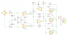
I attached a new schematic. This circuit now uses a voltage divider with R211/R214/R215 to limit the range the dc servo can operate to ~100mV. R211/214/215 in parallel give almost exactly 1kOhms (calculated: 1000.0039) to keep good CMRR of the diff-amp (U202A).
Circuit was simulated and what baffled me ist that the cutoff frequency of the servo was lowered by factor ~100 compared to the version without the voltage divider. To make sure there is no error in the simulation we built the servo circuit on breadboard on Sunday (omitting the buffers) and could measure a time constant increase by factor ~10-20 - hard to tell on the oscilloscope. So it did not conform to the simulated circuit either. The dc servo itself however worked perfectly fine. We did not measure the CMRR, but that simulated fine anyway.
I'd be very much interested in an explanation why the time constant is increased by R211. We even simulated/measured in circuit a version where the output of the servo opamp was connected to ground by an additional 1k resistor because i suspected that loading the servo cap was slowed down by the increased resistance in R211. That did not help at all, neither in the real circuit nor in the simulation.
I can't wrap my head around it! having to use a smaller cap is totally fine by me, it is even beneficial as we can use high quality glimmer caps in relatively small packages now, but i very much would like to understand what's going on here.
Looking forward to your answers...
Cheers, Jürgen
Edit: a 4.7nF cap gave us a time constant of ~2s now. Iow ~0.5Hz.
Attachments
Hi Jürgen,
I had completely missed your previous post. I will draw a picture to explain it, but right now I have no time to do so.
Regarding the cut-off frequency, with the integrator you make a feedback loop around a part of the amplifier. Over the frequency range where this loop has a loop gain greater than one, the gain from amplifier input to amplifier output follows the reciprocal of the transfer of the feedback path. As the gain of the integrator drops by 20 dB/decade, the gain of the whole circuit will increase with 20 dB/decade until the DC loop runs out of loop gain, there it flattens off.
That is, the cut-off frequency is the frequency where the DC loop's loop gain drops to 0 dB. Any attenuator in the loop lowers this frequency and therefore lowers the cut-off frequency. Amplification in the loop has the opposite effect, it increases the cut-off frequency.

Thank you very much! It starts to make sense now.
It also just dawned on me that I got the conversion between time constant and cutoff frequency wrong, because f != 1/Tau. more like f = 1 / (2 * pi * Tau) if I'm not goofing this up again 😕 Things are starting to look up.
One last question, do you see any drawbacks in using this voltage divider after the servo opamp's output? As I said, up to now I can only see benefits - lower cap value needed and possibly reduced injection of noise into the feedback loop.
Last edited:
You also have the 2 pi indeed. With the voltage divider, the offset that the amplifier can handle at its input without clipping the DC feedback integrator gets smaller.
Yes, but that was the whole point of the exercise, we'll never need more than the range of j/- 200mV...
I think you can only handle about 8 mV now. The first stage amplifies that to 80 mV and then you have the ratio between 178 kohm and 1 kohm.
Ah, now I know what you mean. I have to admit that I didn't think of that before, so thanks very much for clarifying that to me!
Actually our gain will be more like 10dB or so for the mid/high section. We will use the gain setting resistor to adjust the whole system's gain structure.
So we'll first decide what gain to use and then adjust the dc offset range to an overall 100mV with R211 to be on the safer side. After that we can choose the dc blocking cap accordingly. Now that the math is known 🙂
Again thanks so much. You made my day!
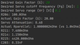
Now I have all the math together I modified my already existing R211/R214/R215 calculator script to read desired gain, cutoff frequency and allowed offset range to also calculate the gain setting resistor and needed dc servo cap. The resistor values are chosen in a sort of monte carlo approach from the E96 series to give best (theoretical) CMRR.
The script can be found here, along with the rest of the project's source files:
_python/attenuator_calulations.py * master * Jurgen Herrmann / AMP-DR * GitLab
The script can be found here, along with the rest of the project's source files:
_python/attenuator_calulations.py * master * Jurgen Herrmann / AMP-DR * GitLab
Attachments
Last edited:
So you got the picture without me even drawing it 😉 ?
To be honest, why the cutoff changes with the dc servo attenuation - I only have a vague clue about it. If you'd find time to draw that up for me, that would be extremely nice! Always happy to learn and hopefully get a better hobby EE designer 🙂
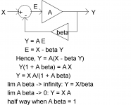
When you look at the general block diagram of a feedback system and write out the equations, you will see that when the loop gain A β is much greater than one, the gain is set by the feedback network (Y = X/β) and when the loop gain A β is much smaller than one, it is set by the forward path (Y = X A). In the picture, half way should be half gain.
The DC servo is a feedback loop around the second part of your amplifier. That is, the signal path including the normal feedback can be seen as A and the integrator as β.
The integrator has a gain that decreases with frequency: suppose you have a sine wave sin(2 π f t) and put it through a circuit that calculates its integral to time divided by RC, then (leaving out an indeterminate constant term) its output will be -cos(2 π f t)/(2 π f RC), so phase shifted and inversely proportional to frequency.
As long as A β >> 1, the gain of the feedback system consisting of the second part of your amplifier and its DC loop is close to 1/β. Hence, it increases with frequency.
When A β << 1, the gain is set by the forward path, that is, by the actual audio amplifier.
The cut-off frequency is at the transition between these two cases, that is, at A β = 1. Due to the phase shift of the integrator, the gain at the cut-off frequency is sqrt(2) rather than 2 times smaller than at higher frequencies.
The integrating circuit itself has a gain of 1/(2 π f RC), but when you put an extra attenuator that attenuates by a factor of k in the DC feedback path, you reduce β from 1/(2 π f RC) to β = 1/(2 π f RC k). Hence, the frequency at which A β = 1 also gets k times smaller.
Attachments
Last edited:
Thanks again very much for the detailed explanation with all the maths broken out into byte sized pieces. Invaluable!
I think I got it now. So if A == 1 (in my case) the any attenuation in the servo feedback path will cause it to shift down the cutoff frequency by that attenuation factor.
Or in other words (I was wondering why an attenuator is used in the examples in this article before: DC Servos) - if A > 1 then to achieve the cutoff frequency calculated by Fc = 1/(2*pi*R*C) you must use an attenuation factor equal to A or otherwise Fc will be shifted up by a factor of A.
Thats something the article completely forgot to mention.
Last edited:
- Home
- Amplifiers
- Solid State
- DC Servo for LPUHP-like amp