With my SIT1s I have removed the film and electrolytic output capacitors from within the amplifier and am using the crossover caps as both DC blocker and high pass filter.
I did this because the caps I was using were too big to fit inside the FW box.
Now I am using smaller caps that would fit inside and I wonder if there could be some advantage to having the DC on the speaker wires and that I should leave it as it is?
Anyone have an opinion on this?
Of course, I will try it both ways but was wondering if there could be some theoretical advantage to this? One (this one, that is) never knows.
Now I am using smaller caps that would fit inside and I wonder if there could be some advantage to having the DC on the speaker wires and that I should leave it as it is?
DC on the cables is not itself trouble, but in case of an accidental short circuit, the amplifier completely will be converted into carbon and smoke.
I have taken sufficient precaution to not have to worry about carbon and smoke.
My (goofy?) thought is if there could be some benefit to the music signal riding on the DC through the speaker cable?
Not the same as those who were placing a DC voltage on the shields of interconnects, of course, but wondering if this "bias" voltage could have a beneficial effect? Or harmful effect, for that matter, on the sound not on the life of the amplifier?
No, as voltage is present between cables, but doesn't flow any current over the cap leak. It only biases the inter-cable capacitance.
The DC will push (pull) the speaker cone outside his "zero", rest point. If < 100 mV no big issue, but it can cause higher distortion as the coil gets out of the magnetic sweep spot whilst in normal function.
How high is your DC on the speaker wires ?
Best,
nAr
How high is your DC on the speaker wires ?
Best,
nAr
The main benefit would be removal of the electrolytic cap from the signal path, which has been presumably replaced by polypropylene caps used in the crossover.
Thanks for all comments.
I have not measured the DC - I will tonight. That is the DC before the cap! If there was DC making it to the JBL 2441's I doubt they would be making any noise at all!
I would figure it is pretty close to the rail voltage minus the drop from all of those resistors connected to the drain of the SIT.
I would rather the caps be in the box - just wondered if there could be something that might make this improper arrangement something to continue.
To change the tune a little - could the coupling caps being placed at the speaker allow more noise into the system?
Over the weekend I will move the caps back and hear if there is any advantage. I hope there isn't and doubt there is. I do wonder if this arrangement makes the amplifier more sensitive to environmental noise .
Thanks for the help!
addition: there is a great advantage to removing the unneeded electroytics. Did it so long ago I cannot remember what pompous flowery prose I would have used to describe the difference but I do remember it being worthy of pompous flowery prose.
Last edited:
Thanks for all comments.
I have not measured the DC - I will tonight. That is the DC before the cap! If there was DC making it to the JBL 2441's I doubt they would be making any noise at all!
I would figure it is pretty close to the rail voltage minus the drop from all of those resistors connected to the drain of the SIT.
I would rather the caps be in the box - just wondered if there could be something that might make this improper arrangement something to continue.
To change the tune a little - could the coupling caps being placed at the speaker allow more noise into the system?
Over the weekend I will move the caps back and hear if there is any advantage. I hope there isn't and doubt there is. I do wonder if this arrangement makes the amplifier more sensitive to environmental noise .
Thanks for the help!
addition: there is a great advantage to removing the unneeded electroytics. Did it so long ago I cannot remember what pompous flowery prose I would have used to describe the difference but I do remember it being worthy of pompous flowery prose.
We all know Papa's work. At least Papa doesn't put caps where unnecessary, so I would put them back into the SiT circuitry - unless you are very sure of what you mean to achieve - for safety of the amps and your speakers
You can replace or bypass any electrolytics output caps by big film qualities ones if you want, you can put them outside the amp if they are to big, just make sure insulation is OK and put the non polarised cap on the + wire, before speaker
Hope this helps,
nAr
Ing. Pass designed the amp to be full range and I am using it above 500 hz.
Amp has been running with out incident due to this arrangement for over a year as I described. I did destroy an output device but that was from dropping a driver which likely shorted the speaker wires. Fuse lived, SIT died. I made my confession to Fr. Pass and know I have not yet done enough penance for this transgression. Amazing how heavy a FOSTEX t500 is ... I guess that could be ascribed to the arrangement but I meant outside of complete stupidity, it is not a cause for concern.
NO WAY I am putting those electrolytics back in! Or replacing the stock input cap.
I think this amp really shines in this application - it is happier not being responsible for the whole range.
Not trying to pretend I know something that Mr. Pass doesn't - I figure if he had a speaker arrangement like mine he would do something similar. Instead of using extra components to effect a high pass filter - this amp HAS to have an input cap and an output coupler - why not trim their values to get the high pass filter the driver requires?
By the way, I agree that Allen Wright is one of the audio greats. The preamp book is the best audio book I ever read. Great sense of humor and ALMOST enough information to build his preamp. I asked him a question about heater-cathode relationships and he told me that was proprietary. OK, in a book that is about how to build the preamp ... Still miss him and appreciate what he taught me.
Ing. Pass designed the amp to be full range and I am using it above 500 hz.
Amp has been running with out incident due to this arrangement for over a year as I described. I did destroy an output device but that was from dropping a driver which likely shorted the speaker wires. Fuse lived, SIT died. I made my confession to Fr. Pass and know I have not yet done enough penance for this transgression. Amazing how heavy a FOSTEX t500 is ... I guess that could be ascribed to the arrangement but I meant outside of complete stupidity, it is not a cause for concern.
NO WAY I am putting those electrolytics back in! Or replacing the stock input cap.
I think this amp really shines in this application - it is happier not being responsible for the whole range.
Not trying to pretend I know something that Mr. Pass doesn't - I figure if he had a speaker arrangement like mine he would do something similar. Instead of using extra components to effect a high pass filter - this amp HAS to have an input cap and an output coupler - why not trim their values to get the high pass filter the driver requires?
By the way, I agree that Allen Wright is one of the audio greats. The preamp book is the best audio book I ever read. Great sense of humor and ALMOST enough information to build his preamp. I asked him a question about heater-cathode relationships and he told me that was proprietary. OK, in a book that is about how to build the preamp ... Still miss him and appreciate what he taught me.
Which speaker do you drive with the SIT amp ?
Did you try the foil (ribbon) speaker cables ?
Best,
nAr
Last edited:
Rick
I believe you're puzzled with fact that in some JBL xovers they put 9V batteries in xover
however , those were put across some caps , to keep them voltage biased , supposedly better sounding that way
also - I know some guys making (commercial even) mains cables with one or two 9V batteries , connected somehow on shield and wherewhocares
in any case - not much benefit of leaving DC between two LS cable wires , so put those (custom values) output caps back where they belong - in amp's case
as I told you previosly - I would leave original ones in situ , while soldering custom valued ones to appropriate output node and routing that to loudspeaker
Nar,
As mentioned each amp drives a JBL 2441 with Truextent diaphragm and a Fostex t500.
Each has its own speaker cable and capacitor. If I place the 18 uF of capacitors back into the box the Fostex will then be fed from the same 18 uF with the 0.8 uF coming afterwards - still at the driver.
ZM, I did not think the mechanism would be the same as biasing caps or biasing the shield on interconnects but I wondered if there could be something to the AC signal riding atop the DC - kind of like priming the pump for lack of a better way of putting it, could there be an electrical equivalent to "stiction" as in bearings/bushings - where it takes more energy to just get the bearing to start moving vs. keeping it going. For automotive guys this is a concern with dampers and bushings in suspensions. Could the DC get the electrons in motion requiring less effort to get them going in the directions required for music to be reproduced? That is my fanciful conception.
Getting the electrolytics out of the way does make a difference. I cannot imagine what good they would do when one does not need the bandwidth they would allow.
I am not alone in experiencing the sonic advantages of doing without electrolytics, especially, in the signal path.
To repeat, I am not having any problems with the arrangement as is. Just wondered if I might have stumbled upon something I should retain.
As always, safety is not my main concern. If it was i would quit smoking cigarettes.
Ok, Rick. Could you make a drawing and post the schematic of your amp / speakers / xover connections ? Just curious.
Your speakers seem homebrew. Just interested in the slopes / frequencies alignment you chose for your drivers ?
Where from comes your assessment that the SIT behaves better when used above 500Hz ? Which is your bass setup ?
Regarding polarizations, I'm not a huge fan of batteries. The DC can't help the electrons flow better I'm afraid. But shielded mains cable do help the speaker output flow, at least in my subjective experience, by reducing mains 50Hz electromagnetic field disturbance near the speaker terminals / cables
Regards,
nAr
.......
ZM, I did not think ........
not trying to put words in your mouth , just guessing possible path of associations , which lead to your dilemma ........ at least these were my associations

nope ..... DC level elevation is veeery beneficial in some areas of electronic, but not here
however ...... having inquiring mind is always beneficial .....

ZM,
My inquiring mind is always dependent on the kindness of minds much greater than mine! Namely yours!
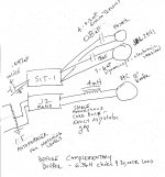
I have attached a very hasty drawing of what is a very simple set-up.
I use Room Equalization Wizard and my ears to set component values for the crossovers. I will try something and listen to it for awhile and then use the computer and see what it says. Speaker system started out as a edgarhorn system. All that remains are the SEISMIC subs. Using John Inlow's papier mache horns for the 2441s and a round horn he designed for the B&C 12s. Sound is big and refined. Been working on this system for twenty years.
I have no idea what is happening above 10K or below 50 hz - don't trust what the computer says - but it sounds right.
AS an aside - I have just installed a bunch of HAMMOND chokes across the AC before and after the SIGNAL DU2s I use for isolation - I was very late to the tweak but have to say those chokes do something that is extraordinary. One DU2 for digital and one DU2 for analog. I use another at the DAC power supply input and another at the phono power supply input. Another pair at each subwoofer (below 40 hz) plate amp power input. Even two, total, made a difference, but more is better.
Not subtle and it continued to get better for about a week before it stabilizes.
Close to magic what it does. I have no idea why it works but i am not complaining. May only apply to US mains.
I use the isolation transformers to block the junk the toroids would welcome into the amplifiers.
My inquiring mind is always dependent on the kindness of minds much greater than mine! Namely yours!
I have attached a very hasty drawing of what is a very simple set-up.
I use Room Equalization Wizard and my ears to set component values for the crossovers. I will try something and listen to it for awhile and then use the computer and see what it says. Speaker system started out as a edgarhorn system. All that remains are the SEISMIC subs. Using John Inlow's papier mache horns for the 2441s and a round horn he designed for the B&C 12s. Sound is big and refined. Been working on this system for twenty years.
I have no idea what is happening above 10K or below 50 hz - don't trust what the computer says - but it sounds right.
AS an aside - I have just installed a bunch of HAMMOND chokes across the AC before and after the SIGNAL DU2s I use for isolation - I was very late to the tweak but have to say those chokes do something that is extraordinary. One DU2 for digital and one DU2 for analog. I use another at the DAC power supply input and another at the phono power supply input. Another pair at each subwoofer (below 40 hz) plate amp power input. Even two, total, made a difference, but more is better.
Not subtle and it continued to get better for about a week before it stabilizes.
Close to magic what it does. I have no idea why it works but i am not complaining. May only apply to US mains.
I use the isolation transformers to block the junk the toroids would welcome into the amplifiers.
Attachments
Last edited:
DC on the cables is not itself trouble, but in case of an accidental short circuit, the amplifier completely will be converted into carbon and smoke.
The amplifier will not care at all, being current sourced by a relatively high
impedance.
- Status
- Not open for further replies.
- Home
- Amplifiers
- Pass Labs
- DC on speaker wire