Hello everybody!!
I have a dc problem on my preamp, and I hope u can help me
find a solution:
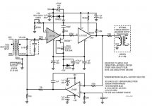
I have built a mic preamp, something like the one in linear tech
lt1115 datasheet, with a dc servo instead of caps in the signal line
For the transformer I used SOWTER 9820, with
5k1 and 220pf for termination.
Instead of the LT1115 I used the OPA627 from TI.
For the integrator I used OPA134, 470n capacitors and
220k resistor (instead the 100k and 1uf).
Now here is the thing, I checked for oscillations and other errors
with my oscilloscope, and everything is fine except that I have
50-200mv on the output!! which changes with gain and frequency.
I couldn't find why, does anyone know??
Thanks!!
The schematic:
I have a dc problem on my preamp, and I hope u can help me
find a solution:
I have built a mic preamp, something like the one in linear tech
lt1115 datasheet, with a dc servo instead of caps in the signal line
For the transformer I used SOWTER 9820, with
5k1 and 220pf for termination.
Instead of the LT1115 I used the OPA627 from TI.
For the integrator I used OPA134, 470n capacitors and
220k resistor (instead the 100k and 1uf).
Now here is the thing, I checked for oscillations and other errors
with my oscilloscope, and everything is fine except that I have
50-200mv on the output!! which changes with gain and frequency.
I couldn't find why, does anyone know??
Thanks!!
The schematic:
Attachments
there still shouldn't so huge dc on output
what's the point of this 2ma current source?
what is the dc at integrator uotput?
what's the point of this 2ma current source?
what is the dc at integrator uotput?
Hi,
The 2ma current source is to bias the opamp in class a.....
The dc on the output of the integrator is changing from -15
to 15 VOLTS depending on the gain setting....
Is this ok???!!!
The 2ma current source is to bias the opamp in class a.....
The dc on the output of the integrator is changing from -15
to 15 VOLTS depending on the gain setting....
Is this ok???!!!
no it isn't for sure
try to skip this 10k resistor to the ground and maybe decrease this 10k r at integrator output
try to skip this 10k resistor to the ground and maybe decrease this 10k r at integrator output
I tried and no change....
Do u think it's because the different primary resistence of the
transformer?
Do u think it's because the different primary resistence of the
transformer?
Anyone have a clue how to measure correctly dc on output?
Either my multimeter or oscilloscope have problem with mixed
signal (AC+ DC)?
Thanks...
Either my multimeter or oscilloscope have problem with mixed
signal (AC+ DC)?
Thanks...
It appears that the +-15V output from the DC servo is not enough to correct the offset of the gain devices through the 10k/10ohm attenuator. Try 100 ohm instead of 10 ohm. It may be also a wiring mistake causing the DC servo to produce positive feedback
To measure the DC component from a waveform with a dominant of AC component just insert a lowpass filter before the multimeter [ie: some resistors and capacitors]
To measure the DC component from a waveform with a dominant of AC component just insert a lowpass filter before the multimeter [ie: some resistors and capacitors]
Hi Eva,
I inserted a low pass filter, butt the scope could also know what
the frequency was (I don't know how because the pole was
at 1 hz!!)
About the dc, i changed the 10r ro 100r but no change,
also i checked wiring and everything is ok.....
the scope reads between 0 and 200mv dc depending on gain,
it takes about few seconds to the scope to settle and show the
exact dc, is this ok??
The funny thing is that i connected the preamp to an amplifier
and could not hear signs of dc as gain is changing...
One to try:
Take out the 10 Kohm at the output of LT1097.
Measure all nodes for DC.
Also see how is now reacts on signals.
BTW: Are you sure that the feedback capacitor at LT1097 really is 1µF (micro farads)?
Take out the 10 Kohm at the output of LT1097.
Measure all nodes for DC.
Also see how is now reacts on signals.
BTW: Are you sure that the feedback capacitor at LT1097 really is 1µF (micro farads)?
The 1uf capacitor is ok, notice that the lt1097 is used as integrator (dc servo).....
I tried what u said, and its still the same... i think maybe my
scope is not ok.....
I tried what u said, and its still the same... i think maybe my
scope is not ok.....
udip said:The 1uf capacitor is ok, notice that the lt1097 is used as integrator (dc servo).....
I tried what u said, and its still the same... i think maybe my
scope is not ok.....
Inspect if any the secondary of the input transformer (Yellow and orange ) is not shorted to ground.
Is the output of the LT1097 sitting at +15V or -15V when the output offset is positive?. Check the same for negative output offsets
Thanks everyone...
The problem has been solved (at least i think so).
I think that my mistake was checking dc offset with input
signal.
When i checked offset with no input with and without the servo
the offset was about 2mv to 2 volts without it (during gain changing) and 0 - 1mv when the servo was connected...
so i think this should be ok, no?


Eva said:It appears that the +-15V output from the DC servo is not enough to correct the offset of the gain devices through the 10k/10ohm attenuator. Try 100 ohm instead of 10 ohm. It may be also a wiring mistake causing the DC servo to produce positive feedback
To measure the DC component from a waveform with a dominant of AC component just insert a lowpass filter before the multimeter [ie: some resistors and capacitors]
I don't think it! If the output of the DC servo is enough to keep the ouput on zero, it goes up or down to rail (say +/-15V), and keep it. No moving between the rails. As I see, the servo can regulate 15-18mV offset on the input. which looks enough to me.
So I think, this is low frequency oscillation. I had this problem with one of my amplifier. The typical sign is the slow triangle wave on the output of the DC servo.
Maybe the transformers cause this problem. I would try to use non inverting DC servo and connect it to the pin2 of the LT1115 via 33-47k series resistor.
sajti
sajti, I think you are right..
I checked on scope and I can see a triangular wave on the output
of servo with input, but only with low frequency.
That's servo oscillation?
If i put a non-inverting servo to the - input of opamp, should I
use some sort of bias to the + input in order the eleminate the
feedback to ground capacitor?
Thanks...
- Status
- Not open for further replies.
- Home
- Amplifiers
- Solid State
- DC on output