Could someone please explain, or point me to a tutorial on DC offset. Or tell me in simple terms "what it is". I've searched the forum and the net. Lot of articles. But none just come out and says it simple enough for me. I'm not exactly a beginner, I've built a lot of amps. I know and use ohms law but I only have a volt-ohm meter and just use the trial and error method. Is the DC offset the reason for putting a resistor directly to ground on the input? Is there a formula for this resistor? How do I measure DC offset - just put my volt meter on the amp input with no input device connected? Is this DC offset also a problem on the output? I've never blown a speaker, so surely I'm doing something right.
Have read this forum word for word for a year now, and literally having a blast. Thanks so much for all the info.
Have read this forum word for word for a year now, and literally having a blast. Thanks so much for all the info.
DC offset is a net, no-signal DC voltage measured at the amplifier output, which should be zero. DC is unhealthy for speakers...
The input resistor is not strictly for determining DCO, although it does establish a zero reference for the input signal. It determines input impedance.
It's possible for a small input-offset (eg due to DCO of source) to become amplified at the output. This is commonly avoided by using a series capacitor at the amp input or between ground and the second feedback resistor. A separate servo for DC feedback can also be used.
Does this mean that my volt meter should not register any DC voltage on the output to the speakers? Is that not what the output capacitor is for - to block the DC?
willy said:Does this mean that my volt meter should not register any DC voltage on the output to the speakers? Is that not what the output capacitor is for - to block the DC?
Indeed, your voltmeter shouldn't register a DC voltage on the output.
And yes, the output capacitor is also for blocking DC. However, output capacitors are not normally used to block small (<100mV) DC offsets. The whole point of a direct coupled (no output cap) is that you don't have/need a output capacitor.
But some amps (with a single supply, say from 0 to 20V) have the output of the output transistor at half the supply voltage. Output caps are necessary for those amplifiers (else, you would have a 10V dc voltage at the output and no way to get rid of it)
DC-offset
To add to earlier posts. It's virtually impossible to achieve exactly 0V DC offset over the entire temp / power range of an output stage without capacitor.
A DC offset within a range of +/- 50 mV is acceptable, lesser values are preferred.
EG: My DIY JLH amp changes from +40mV (after an initial peak of 150mV) at startup to somewhat in the region of +/- 3mV over an hour warming up depending on ambiant temp.
Thanks so much members for those simple, easy to understand explanations. One of the things that was throwing me off was that all the amps I have built so far have single supplies. So I''ve always got about half the supply voltage on the output.
Willy,
One drawback of using that topology is that the output cap has to be very large if you want your amp to work down to very low frequencies. Direct-coupled designs generally don't have this problem. It is also best to avoid having the signal pass through a capacitor if possible, to avoid introduction of capacitor-induced distortion.
Most designs nowadays are direct coupled.
Regards
Shaun, you are a bit unclear. If you have an amp with fed only with single supply, you must have a capacitor at the output, (unless it is bridge connected) and if you have dual supply as most amps have you never use an output cap.
Yes, of course. Sorry about that. Some designs need the output cap.
I always believed that the main purpose of this resistor was to establish DC refence to ground, and that the input impedance was a consequence of the resistor value.
DrG:
The input resistor is not strictly for determining DCO, although it does establish a zero reference for the input signal. It determines input impedance.
I always believed that the main purpose of this resistor was to establish DC refence to ground, and that the input impedance was a consequence of the resistor value.
Shaun, not quite right. The resistor to ground creates a DC path crucial if the input has a DC blocking capacitor. Without this resistor the amp won't work at all.
Let's get on the same page first
I'm probably in error in referring to the wrong resistor as the input resistor.
R1 is the actual input resistor, but I was really referring to R2 (as the discussion had originally been about DC offset). Please see the diagram.
Which resistor has greatest impact on input impedance (my own amp has a 100k at R1), and am I wrong about R2 being the DC sense point for the amp input?
PS- I'm not being difficult here, I just need to know for sure.
Regards
Attachments
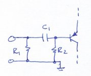
The R1 is optional but I use to have some pull down, 100k - 1 Mohms, just preventing the cap to pick up charges. Both resistors have influence but only R2 has influence on the offset. R1 can be any high value but R2 must be "tweaked" not to disturb to much. The value is dependent of how much bse current you have, how much offset and how low input impedance you can take.
Note that base current through R2 creates a voltage.
If you want to get a picture of the problem, check datasheets and especially the offset trim section for a "bad" opamp like NE5534 which has rather large input bias current and also rather high offsets.
If you have understood the theory behind the problem you can easily use the knowledge at your discrete amp.
Good reading here
http://focus.ti.com/docs/apps/catalog/resources/appnoteabstract.jhtml?abstractName=sboa092a
Can anyone give me a hint where I can find the 300 page document from texas in the subject?
Thanks, I can sleep better now
That is exactly as I understood it. Sorry for the wrong terminology in my previous posts.
Just a question about R1: does this (high) value contribute much to noise?
Regards
That is exactly as I understood it. Sorry for the wrong terminology in my previous posts.
Just a question about R1: does this (high) value contribute much to noise?
Regards
Think like this: ALL resistances between the signal source and the amp. If you have both series and parallel resistors you must convert them to a single one. The noise resistance is what the input (the input transistor) "sees". Usually ONLY the signal source resistance and .... the feedback network have influence on the noise (including the noise internally in the amp).
The answer is: NONE to your specific question.
The answer is: NONE to your specific question.
Oops- you've edited your post
Yes, Peranders. I think I understand.
The heavier the base current, the more important it is for the dc impedances (looking out of the base) to be equal, in the case of a differential input amp. Else the resultant imbalance in the input standing currents will cause a dc offset at the output.
Yes, Peranders. I think I understand.
The heavier the base current, the more important it is for the dc impedances (looking out of the base) to be equal, in the case of a differential input amp. Else the resultant imbalance in the input standing currents will cause a dc offset at the output.
- Status
- Not open for further replies.
- Home
- Amplifiers
- Solid State
- DC Offset Question