Hi!
I have a problem that almost cost me my speakers. I have a power supply of 10000uF per rail, the transformer is 2X18AC 150VA and also I have blue alps pot. When the pot is on minimum the DC offset is around 10mV but when I turn it up the DC offset goes to the 140mV . Also i have gain around 40. What would solve my problem.
Greatings
I have a problem that almost cost me my speakers. I have a power supply of 10000uF per rail, the transformer is 2X18AC 150VA and also I have blue alps pot. When the pot is on minimum the DC offset is around 10mV but when I turn it up the DC offset goes to the 140mV
. Also i have gain around 40. What would solve my problem. Greatings
probably a cap in the feedback network, so DC is not amplified anymore.What would solve my problem.
regards
Picture this: You have a constant current into the input of the IC (input bias current). If you have the input shorted the voltage drop will become zero + the voltage offset. If you have 10 kohms times the current = 2-10 mV amplied 40 times. You have a varying resistance from the input down to signal ground, that's why you'll the change when you turn up the volume. You may also have a small DC voltage from your signal source. Why do you have so much gain? 20-30 is normal.mravlcax said:When the pot is on minimum the DC offset is around 10mV but when I turn it up the DC offset goes to the 140mV
As this thread is in the chipamp section ... Did you all talk about a Gainclone ? Is the chip in single or parallel or even bridged parallel operation ?
Interesting answers up to now, but I could never give any suggestions before i wouldn't have known these facts or even a closer look into a small part of schematic ...")
But if it is really a sort of gainclone chip like LM3875/3886, why don't you use a DC-Offset regulator circuit to fix this problem ? Adding a cap in the Feedback would not be my favorite.
best regards
artQuake
Interesting answers up to now, but I could never give any suggestions before i wouldn't have known these facts or even a closer look into a small part of schematic ...
But if it is really a sort of gainclone chip like LM3875/3886, why don't you use a DC-Offset regulator circuit to fix this problem ? Adding a cap in the Feedback would not be my favorite.
best regards
artQuake
of course seeing the schematic first, would be preferred.Interesting answers up to now, but I could never give any suggestions before i wouldn't have known these facts or even a closer look into a small part of schematic ...
But reading a while in the chipamp section, gives one a good picture of the usual suspects.
It seems that beginners often make the same mistakes and rely on questionable implementations circuling around the net.
regards
Offset problems is question number 2 and number 1 is hum.artquake said:Interesting answers up to now, but I could never give any suggestions before i wouldn't have known these facts or even a closer look into a small part of schematic ...
Indeed and they don't look for applications notes nor datasheets. This is the first thing I look for if I want to use an unknown part.Juergen Knoop said:
It seems that beginners often make the same mistakes and rely on questionable implementations circuling around the net.
regards
use an AC coupled topology for the chipamp.
That requires a DC blocking cap between the source/pot and input and also a DC blocking cap on the lower leg of the gain setting NFB loop.
This topology prevents inadvertent pass through of DC from a source or from variable source impedance due to an unbuffered pot.
That requires a DC blocking cap between the source/pot and input and also a DC blocking cap on the lower leg of the gain setting NFB loop.
This topology prevents inadvertent pass through of DC from a source or from variable source impedance due to an unbuffered pot.
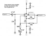
This is a chip amp and it is a LM3886. The schematic I used is from THIS.
Peranders thank you for explanation what DC offset is. The gain so high because I use it with an old tuner that has low signal, I know it would be better if I used a preamp but this is only a workshop amp. And yes I didn't read much about it, just searched for simple design and build it.
But you guys really know your job well and answered me within an hour.
Greatings
As I read thorugh the datasheet of the LM3886 and some other designs I moded my chipamp. Now I have gain of 30 simply by replacing the 560ohm resistor with 680ohm, added 47uF capacitor in the feedback network and on the input I added 4,7uF DC blocking capacitor.
But I still noticed that the speaker membrane is going a bit out when I turn up the pot to the max. But this only happens when I have it connected to the sound card Audigy 2. On other sound cards this doesn't happen. So it could be a sound card problem?
Greatings
But I still noticed that the speaker membrane is going a bit out when I turn up the pot to the max. But this only happens when I have it connected to the sound card Audigy 2. On other sound cards this doesn't happen. So it could be a sound card problem?
Greatings
Hi,
I wonder if the input cap is passing DC (excessive leakage current) to the amp input?
Is the Pot before the blocking cap?
The NFB cap is too low compared to the value you have use at the input. Change the 47uF to 220uF.
The 1k0 is a separate issue related to the missing RF filter.
You should add the 1k0 between the cap and the 22k and also add a cap in parallel to the 22k. A value between 330pF and 1.5nF is suitable . Try 680pF as a starter.
I'm not shure, if the resistor would help.
Is there still significant DC at the output?
There shouldn't be more than a few mV and it should be independant of the volume pot setting.
If you have the parts at hand, you could add the zobel and output inductor//10R.
Maybe there is some sort of RF or oscillation problem.
regards
Is there still significant DC at the output?
There shouldn't be more than a few mV and it should be independant of the volume pot setting.
If you have the parts at hand, you could add the zobel and output inductor//10R.
Maybe there is some sort of RF or oscillation problem.
regards
- Status
- This old topic is closed. If you want to reopen this topic, contact a moderator using the "Report Post" button.
- Home
- Amplifiers
- Chip Amps
- DC offset problem