Dxvideo said:I suspicied that MOSFET sinks a huge current from gate.
It looks like you did damage the MOSFET - it is easy if you do not observe antistatic precautions carefully. If the gate is broken you would have a big leakage current through the gate. That is what the zener for - to protect the gate. Do not remove it. Replace the MOSFET and this time be careful - at the very least put a strip of foil or a copper wire around the pins of the MOSFET before handling and soldering it in to the circuit and do not forget to remove it after you've soldered it in.
Cheers
Alex
Dxvideo said:Dear Alex,
I dont know the reason but I cannot adjust the bias voltage!
I've tried 150K+20K Trimpot+56K, 100K+20K Tr.+10K even 100K+20K+1K and without zener. However I couldnt get over 1,6v offset at gate.
At 100K-1K combination I can get only 1,6 v not more!
I am really confused. Whats the G-S resistance of that MOSFET? I suspicied that MOSFET sinks a huge current from gate. Then I cannot stabilise the mid point of voltage..
What do you say?
Thx again.
A mosfet's gate is isolated - it CANNOT conduct current in any circumstances! (unless it is punctured and destroyed.
it is still missing the coupling cap, without that the bias wouldn't work
@dxvideo:
did you tried the adjustments with or without the suggested cap?
regards
@dxvideo:
did you tried the adjustments with or without the suggested cap?
regards
Hi Christer,
re post20 circuit.
Will the opamp automatically bias the FET gate to zero the DC offset at the output?
What happens to voltage swing from the opamp? Will it cause asymmetric clipping done this way?
re post20 circuit.
Will the opamp automatically bias the FET gate to zero the DC offset at the output?
What happens to voltage swing from the opamp? Will it cause asymmetric clipping done this way?
Dear friends,
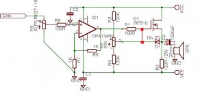
I found my mistake finally. I havent tried yet but, when I am adding the capacitor between op-amps output and MOSFET s gate, the op-amps feedback resistors was in the front of that cap. So the bias voltage always at 0 volts because of the feedback resistor goes to the gnd via just one 1K as you can see in the schematic. And my pull up and pull down resistos are about 100K levels. So I couldnt adjust +4v point. Tomorrow I will fix the problem. And report you the results.
However I am still confused, how it was working under that situation. The sound was really incredible!
This is the mistaken connection;
An externally hosted image should be here but it was not working when we last tested it.
AndrewT said:Hi Christer,
re post20 circuit.
Will the opamp automatically bias the FET gate to zero the DC offset at the output?
That was the intention yes. Did you spot any errors?
What happens to voltage swing from the opamp? Will it cause asymmetric clipping done this way?
Yes, but I think all variants so far will clip assymetrically anyway. The MOSFET gate must be biased at least 3 or 4 Volts above ground. Maybe one could get rid of that problem in some cases if keeping the output cap, but the idea was it could be omitted in my version although I kept it in the schematic.
Hi Christer,
I see no errors in post20.
But what about a couple of changes?
Take the speaker/headphone return to Vcc instead of to ground.
Replace R2 with a constant current sink (somewhere between 100mA and 200mA).
Maybe add a 2mA sink from pin6 to Vee to convert the opamp to single ended output stage.
Now, we have a truly constant current amplifier where the load current in the supply rails does not vary with signal level, provided the single ended stages do not clip.
Adding one DC blocking capacitor to pin 3 and a couple of resistors converts the whole amp to single polarity power supply. Just connect the grounds to Vee, in the correct order.
Andrew, there is a lot of things one could do. My suggestion wasn't intended to be optimal in any sense, but just one type of solution with minimal changes from the original.
I think my edited schematic doesn't need a coupling capacitor.juergenk said:it is still missing the coupling cap, without that the bias wouldn't work
I don't see why it doesn't work.
Dear Zing,
Your "edited" drawing is same as my first circuit exactly. If you examine my first drawing, you'll see.
Anyway, It already works fine with that situation (and I cannot understand how?) , yes I feel some treble weakness but I hear no distortion or noise.
Your "edited" drawing is same as my first circuit exactly. If you examine my first drawing, you'll see.
Anyway, It already works fine with that situation (and I cannot understand how?) , yes I feel some treble weakness but I hear no distortion or noise.
Hi,
only a cap could isolate the bias circuit from the opamp
which you have recognized yourself
regards
because of the feedback, opamps output is a zero impedance dc-source, the 100R resistor does not helpzing said:
I think my edited schematic doesn't need a coupling capacitor.
I don't see why it doesn't work.
only a cap could isolate the bias circuit from the opamp
it works for ac, but it does not work for dcAnyway, It already works fine with that situation (and I cannot understand how?)
which you have recognized yourself
regards
Hi,
it might help understand what is happening if you use the standard rule for opamps:
the output tries to settle at a voltage so that the two input pins are at the same voltage.
Now working back from that statement.
If the two input pins are both at zero volts, then you can work forward through the resistors to calculate what DC voltages need to be at the various points to get the circuit to be DC stable.
This will result in the output cap sitting at -Vgs.
If instead you work backwards from the output and assume zero volts at the source pin, then what voltage will appear on opamp pin2. Now using that same rule what voltage must pin3 be biassed to? This can be done with three resistors and a DC blocking cap.
Once you understand what the circuit is supposed to do then it becomes easier to design it to make it do what you need.
Thank you, juergenk!juergenk said:Hi,
because of the feedback, opamps output is a zero impedance dc-source, the 100R resistor does not help
only a cap could isolate the bias circuit from the opamp
I misread R1 as 100k without thinking of such a high resistance would cause HF roll-off back then. What a fool! :0)
Hi all,
I am fixed the unadjustable bias problem. Its now +4v and the offset on output is about 0v.
But now I have the unstability problem. DC offset voltage always swinging. I wait until the MOSFET comes to 55 C for bias adjusting. However while the temperature was stable output DC offset was still decreasing. And I had to put the 1500uF on output again.
But the sound is beatiful. No noise or distortion. The mids and trebles are very detailed. And the basses are impressive!
This is the last situation of the circuit;
It works fine and HOT! But there is -2mV offset on each channel after warming up.
Do you think that make problem?
An externally hosted image should be here but it was not working when we last tested it.
It works fine and HOT! But there is -2mV offset on each channel after warming up.
Do you think that make problem?
Hmmm... Good question. I havent tried that! I dont hear any noise while volume adjusting via pot. However technically, I am changing the input load and I have DC coupling so it must be changed.
I will test that.
Thx Andrew
I will test that.
Thx Andrew
- Status
- Not open for further replies.
- Home
- Amplifiers
- Headphone Systems
- DC Offset on Class A headphone amp.