I have an audiosector LM3875 kit with high offset numbers: One channel is as high of 186 mv. I can lower the DC to 95 by loosening the screw that attaches the amplifier to the sink, but in this case the amplifier hardly touches the heatsink. In fact, by merely putting the amplifier next to the heatsink the DC jumps up to 186. I have tried placing an 47 uf electrolytic between the one end of 680 ohm resistor and the chassis ground, but this had no effect on the DC.
Do you think there is something with my amplifier (the other amplifier has a DC of 96mv.)? Is there anything else I can do to lower the DC figures?
Thanks in advance for any help you can give.
Do you think there is something with my amplifier (the other amplifier has a DC of 96mv.)? Is there anything else I can do to lower the DC figures?
Thanks in advance for any help you can give.
The chip needs to be attached firmly to the heatsink for proper heat dissipation. The force with which chip is attached shouldn't affect DC offset reading.
The only explanation would be that with loosening the screw, the chip gets excessively hot because it's not in contact with heatsink and that reduces the offset.
What if the offset reading with source connected?
The only explanation would be that with loosening the screw, the chip gets excessively hot because it's not in contact with heatsink and that reduces the offset.
What if the offset reading with source connected?
Thank you, Peter. Your explanation makes sense since the DC reading increases simply when with my hand I put the chip next to the heat sink.
As to the DC reading when it is connected to the source, It fluctuates between 167 and 188 mvolts in one channel and it is about 80 in the other.
As to the DC reading when it is connected to the source, It fluctuates between 167 and 188 mvolts in one channel and it is about 80 in the other.
So it means that your source is coupled through a capacitor, as with DC coupled outputs the offset will normally go down.
More info on offset here: http://www.diyaudio.com/forums/audi...-kit-building-instructions-5.html#post1523699
You could change shunt resistor value (R2) from 22k to 10k and this should reduce offset.
More info on offset here: http://www.diyaudio.com/forums/audi...-kit-building-instructions-5.html#post1523699
You could change shunt resistor value (R2) from 22k to 10k and this should reduce offset.
Hi, I've just completed my Audiosector LM3875 build. The proto build sounds really good and there is no hiss or funny noises coming from the loudspeakers. ")
DC offset is around 4 mV on the right side and around 20-25mV on the left side. I've visually checked the soldering and all seems ok.
Although 20-25mV is not much, what could the reason for the difference between the left and right channel be ? Is it a concern ?
Thank's
Rupert
DC offset is around 4 mV on the right side and around 20-25mV on the left side. I've visually checked the soldering and all seems ok.
Although 20-25mV is not much, what could the reason for the difference between the left and right channel be ? Is it a concern ?
Thank's
Rupert
Attachments
ah, ok ... thank's Andrew,
from what I see here it looks like each LM3875 has its own DC offset values (I think ?)
So, in my case if I understand correctly there is nothing to worry about ?
I have the amp playing in my main system without a hiccup so I'm guessing all is OK.
Tauro, I did the measurements with / without the inputs shorted and in both cases the values where more or less identical.
Thanks for all your input.
All the best
Rupert
I always recommend AC coupled Power Amplifiers to all inexperienced Builders.
Then when the experience allows you to foresee the dangers and you become able to design the various add-ons to protect your speaker and amplifier, you can then take the informed decision of whether to adopt DC coupling.
Then when the experience allows you to foresee the dangers and you become able to design the various add-ons to protect your speaker and amplifier, you can then take the informed decision of whether to adopt DC coupling.
I have left the amp on for a while and the DC values have shot up to close to around 190mV on both channels
Listening levels where low and heat dissipation on the chips negligible.
I unplugged the amp and left it for the night. Next morning I got the same values.
As I understand it is the source (DAC with preamp) which is injecting the DC. The strange thing though is that with any other amp connected to the DAC there is no more DC on the Loudspeaker terminals than usual.
Could this be linked to a grounding issue (CHG is not connected yet ? The build is still on a piece of wood).
With shorted input terminals the build measures around 27-28mV on one and around 5-6mV on the other channel which seems very reasonable.
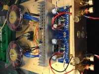
That's also what I'm doing in all my stereo amps and in the picture below I'm showing trouble free way to connect power grounds: output grounds of both channels (OG) are connected with a piece of thick copper wire. Central point on that wire is power star ground and all 4 ground wires from rectifiers board (PG+, PG+ and PG-, PG-) are connected here. Output grounds are taken directly from the board, signal ground connects to the point on the board marked as SG.
Is this still the way to do proper grounding on the newer blue boards ? please see post 522
Is this still the way to do proper grounding on the newer blue boards ? please see post 522
If using a single transformer then yes, this is a preferred method of grounding.
I have left the amp on for a while and the DC values have shot up to close to around 190mV on both channels
Listening levels where low and heat dissipation on the chips negligible.
I unplugged the amp and left it for the night. Next morning I got the same values.
As I understand it is the source (DAC with preamp) which is injecting the DC. The strange thing though is that with any other amp connected to the DAC there is no more DC on the Loudspeaker terminals than usual.
Could this be linked to a grounding issue (CHG is not connected yet ? The build is still on a piece of wood).
With shorted input terminals the build measures around 27-28mV on one and around 5-6mV on the other channel which seems very reasonable.
It's not a problem of grounding, this amp will amplify any DC present at its input, because there's no capacitor between R3 (680R) and ground.
To avoid any excessive offsets at the amp's output, you have 3 options:
- use a source with no DC offset
- use input coupling capacitor (2.2uF or bigger, can be installed in place of R2)
- or use capacitor between R3 and ground (22uF or bigger)
DC offset is around 4 mV on the right side and around 20-25mV on the left side. I've visually checked the soldering and all seems ok.
Although 20-25mV is not much, what could the reason for the difference between the left and right channel be ? Is it a concern ?
As stated before, the offsets will vary with chips: some chips show much bigger offset values than other in this particular circuit
20-25mV is nothing to be concerned and anything less than 80mV or so is still fine.
It's not a problem of grounding, this amp will amplify any DC present at its input, because there's no capacitor between R3 (680R) and ground.
To avoid any excessive offsets at the amp's output, you have 3 options:
1 use a source with no DC offset
2 use input coupling capacitor (2.2uF or bigger, can be installed in place of R2)
3 or use capacitor between R3 and ground (22uF or bigger)
Hi and thank's All for the input !
I cannot change the source it is the only one I have
I is a Yulong DA8 DAC i payed a fortune for
So I guess I'll put a input coupling capacitor in R2. What is the advantage of point 2 over 3 ?
Thank's !
Rupert
PS. I still don't understand why the measurements changed so much in the course of 3 or 4 hours of continuous playing music at normal levels ?? Probably my Yulong ? I hope not.
Last edited:
It's most likely Yulong changing it's output offset.
As to advantage of pint 2 is that you can use much smaller cap, so better quality and you actually protect the amp against any possible offsets from sources.
Point 3 only prevents amplifying of the offsets. The amp has approx 32x gain (or 30dB) so if the the source offset is 5mV you will see 150mV at the amp's output.
The possible advantage of point 3 is that the cap, although much bigger, is not in direct signal path so it's effect may not be that obvious. Although, OTOH, there's no such thing as component not in a signal path, everything actually matters.
- Status
- This old topic is closed. If you want to reopen this topic, contact a moderator using the "Report Post" button.
- Home
- More Vendors...
- Audio Sector
- dc offset of 180mv.