I keep reading (here) that toroidal transformers used as PP OPT are much more susceptible to saturation than conventional transformers. Why is this.
Correctly me if I wrong. The flux and hence saturation is proportional to current whether AC or DC. Ok so if you apply a small DC voltage then yes the current is limited only by the resistance of the windings, but a valve output would just have a current mismatch between legs, and both a toroidal and conventional transformer would saturate at the same current point for the same output power rating. So I cannot see why there would be a difference?
Correctly me if I wrong. The flux and hence saturation is proportional to current whether AC or DC. Ok so if you apply a small DC voltage then yes the current is limited only by the resistance of the windings, but a valve output would just have a current mismatch between legs, and both a toroidal and conventional transformer would saturate at the same current point for the same output power rating. So I cannot see why there would be a difference?
Flux density in a cored inductor will depend on:
-DC current
-AC voltage
With AC voltage, it is an alternating flux.
They are also calculated differently and depend of different things.
Alternating flux, for a sinewave signal, Bac = Vrms / Turns x Core eff. area x Frequency x 4.44
DC flux however, Bdc = Inductance x Idc / Turns x Afe.
In the DC flux situation, the more inductance we have, the more sensitive to DC current is the transformer. Sensitive means more DC flux per DC current.
If we decrease permeability, we decrease inductance. Inductance is proportional to permeability.
So in inductors with cores, such as a SE transformer or a PSU DC filter choke, often an additional gap, an air gap is inserted, which kills overall permeability, hence decreasing inductance and making the overall device more DC tolerant.
Last edited:
In push pull the current from positive winding and negative windings should cancel out and so have zero current flow. At least it will if valves and cathode resistors are matched.
I keep reading (here) that toroidal transformers used as PP OPT are much more susceptible to saturation than conventional transformers. Why is this.
Correctly me if I wrong. The flux and hence saturation is proportional to current whether AC or DC. Ok so if you apply a small DC voltage then yes the current is limited only by the resistance of the windings, but a valve output would just have a current mismatch between legs, and both a toroidal and conventional transformer would saturate at the same current point for the same output power rating. So I cannot see why there would be a difference?
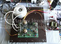
Due to nature of toroidal cores they have higher permeability (with same material) compared to C-cores and especially EI, and thus, higher parasitic DC flux density because of imbalance of output tubes.
It can be solved (toroid on a photo attached handles several mA of DC imbalance without any problem), yet I don't think it worth extra effort and cost involved.
Attachments
Conventional transformers have gaps between the lamination pieces (even if they are touching, its not perfect as the lams are stamped), a wound toroidal core doesn't have gaps. Gaps are extremely important in core materials with high permeability - they typically control the actual permeability.
For instance iron alloys can have (relative) permeabilities in the 2000 to 200000+ range, but with 0.1% of the magnetic path being a gap the overall permeability of a core is clamped to no more than 1000.
Higher permeability means reaching saturation flux-densities much more easily. thus limiting the DC current before saturation.
Limiting the permeability does limit the inductance too, that's the downside.
Not in a transformer. The net MMF generated by the AC is normally tiny, since the primary and secondary AC amp-turns cancel each other to a large degree. The DC is not cancelled.Correctly me if I wrong. The flux and hence saturation is proportional to current whether AC or DC.
Last edited:
You "should" be able to make Toroids way better, DC wise, IF you could cut a slit in rings with some kind of tool.
Practical problem is silicon steel is too hard and brittle (so not machining friendly) and cutting tools (disk saws o grinding wheels) are not thin enough.
It IS done on C cores, where mating surfaces are polished flat and then *you* add some thin insulating material to have a precise, custom gap.
Practical problem is silicon steel is too hard and brittle (so not machining friendly) and cutting tools (disk saws o grinding wheels) are not thin enough.
It IS done on C cores, where mating surfaces are polished flat and then *you* add some thin insulating material to have a precise, custom gap.
Simpler solution...parafeed the toroid. The parafeed cap blocks the DC.
I built an amp with 6C33C output tubes and surplus-store power toroids.
8WPC, -3dB at 15 and 40K Hz. A great sounding amp!
I built an amp with 6C33C output tubes and surplus-store power toroids.
8WPC, -3dB at 15 and 40K Hz. A great sounding amp!
In my books the flux is just proportional to current. However for a transformer with a secondary at DC the secondary does nothing. However for AC the secondary when loaded will reduce the flux level (I think) so there is a difference between transformers and inductors. So by taking energy out of the secondary you are reducing the AC saturation compared with DC. I get the stuff about the permeability being much higher - and gapping a toroid. Thanks Mark I see why they are different.
Last edited:
In my books the flux is just proportional to current.....
What books?
Magnetic flux is Volts times Time. No current is needed. Audio transformer saturation is usually about too much voltage or too long a time (too low a frequency).
Iron powder toroids, used for audio OT have a "distributed gap" built into the core. No need to cut a physical gap into it. Core manufacturer data will show saturation current. But OT makers don't show that. Read more here (answer):Electronic – Can a “distributed gap” powdered-iron or ferrite toroidal core be used for a flyback converter’s coupled inductor – iTecTec
My toroidal PTs as OPT setup can handle a mismatch of 10's of mA, but I balance it with CCS on small amps and auto grid biasing on larger ones. I get more bandwidth and less phase shift, too.
I'd sell my Hammond OPTs (1650N) in a heartbeat...
I'd sell my Hammond OPTs (1650N) in a heartbeat...
With cut cores, one could insert a -very- thin wafer of Neodymium magnet into the two core gaps, to pre-bias the core opposite to the DC magnetization. The problem is that Neodymium would short out the AC flux by its shorted turn effect and conductivity. Ferrite permanent magnet won't have the needed strength, and the wafer needs to be -very- then, or else you just end up with an effective air gap and low effective permeability.
--------
A toroid could be made with a thin coating of permanent magnet material plated onto one or two flat sides of the magnetically "soft" steel band material and then wound up into the toroid.
A strong pulse of counter DC current thru the core could then pre-magnetize the permanent material so as to pre-bias the core to counter the subsequent tube DC.
(I mentioned this scheme many years ago)
The distributed permanent magnet material all acts in parallel (area) to produce the counter "bias" field, and is thinner than the lamination material (against AC eddy currents). It could also be plated on as stripes to eliminate even better any eddy current shunting.
------
Another scheme would be to use a special winding on a standard toroid core and pulse that with HF DC pulses to counter the tube DC. (above audio band pulsing) The pulse mode would allow a Mosfet to operate that efficiently (pulsed On/Off mode) from LV DC. Some ferrite cores in the other audio winding leads to keep the pulses from going elsewhere. (effectively a HF pulsed counter CCS)
Last edited:
There are cut gapped toroidal cores, but I guess they are a custom order article.
A down side is the little to none flexibility of controlling the permeability once a toroidal gapped core is made. It can either be further ground, filled with ferromagnetic glue or grease, probably clamped and glued, but not the versatility of different gap thicknesses that can be inserted into C cores or EIs.
With EIs you even have the flexibility of variating the lamination interleaving pattern.
A wafer of anything is NOT a shorted turn because it is not "a turn" by any means.With cut cores, one could insert a -very- thin wafer of Neodymium magnet into the two core gaps, to pre-bias the core opposite to the DC magnetization. The problem is that Neodymium would short out the AC flux by its shorted turn effect and conductivity
1) it does not go fully around the core. (so not a turn)
2) it is in series, not in parallel, with the rest of the core
A wafer of anything is NOT a shorted turn because it is not "a turn" by any means.
1) it does not go fully around the core. (so not a turn)
Putting some copper or other conducting metal sheet into the gaps of a cut core, or any SE OT, will ruin the performance and get hot besides. This is how eddy currents occur and is the reason for using insulated transformer laminations to prevent them.
2) it is in series, not in parallel, with the rest of the core
The shorted turn is just like another secondary, except shorted.
series/parallel????
There will fringing flux, high flux density around the airgap. It makes sense a piece of metal there can overheat under some conditions. At least this topic is regarded as a serious problem in some inductor situations. Due to fringing flux, nearest copper wires can start increasing temperature.
I have no depth knowledge of this phenomena, IIRC it was more of an issue in SMPS uses.
I have no depth knowledge of this phenomena, IIRC it was more of an issue in SMPS uses.
Last edited:
FYI:
Re: Fwd: Pytanie o produkt TTG-KT88PP - Tube output transformer [4kOhm] 2xKT88 / 2x300B Push-pull or similarHello.
Up to 5% current imbalance does not cause significant harmonic distortion.
Above 5%, low-frequency distortion begins to become apparent.
Best Regards / Serdecznie pozdrawiam,
Tomasz Lachowski
------------------------------------------------------------------
TOROIDY.PL Transformatory L. Lachowski Sp. k.
Kolonia Koplany 1E
16-061 Juchnowiec Koscielny
phone: +48 85 733 77 73
Transformatory toroidalne - Producent transformatorow Toroidy.pl
info@toroidy.pl
- Home
- Amplifiers
- Tubes / Valves
- DC offset in toroidal OPT causing saturation