Have acquired a set myself and am curious as to how your project is coming along. My 777 and 776 are from the original owner and not used much at all. Waiting to see if the battery will take a charge.
Have you completed the mods that you discussed in your posts on both these pieces? Not personally understanding the technical details of what was discussed, but am perfectly capable of doing the soldering and parts replacement. Could you supply a list of the parts you replaced and the replacement part details?
Would be greatly appreciated as I doubt that I will find anyone who can do any real work on these.
The transformers in the amp bear a date of 12/82 and the preamp transformer says 10/82. Not sure where in the production run this puts them, but a brochure I have seems to indicate that these started production in the late 70's so that would put mine in the last year of production.
They came with a pair of 770 speakers, a 775 Turntable, a 774 tonearm with Nagaoka MP50 cartidge, the 776 and 777 and a Nakamichi ZX-9 tape deck. All are in great shape and I'd like to put the set back to work without damaging anything.
TIA
Peter
That's a nice combination. I've owned just about every one of those at some point in time. I still have the 770's. The discovery I made was that the 777 amp's DC offset varies with the source impedance connected to it's input. When the 776 is on the output inpedance is 250 ohms. When it is off the output relays short making the output impedance zero. The 777 has two resistors in the input circuit which are factory selected to give the lowest DC offset. They vary from amp to amp, channel to channel. Remember the 777 is an identical dual mono setup. The problem is the factory doesn't know what preamp you are going to use and thus pick the resistor value to give the lowest possible DC offset over the range of common preamp output impedances. If your preamp happens to to be in the proper range then you are OK. With my 776 turned on the 777 produced a DC offset of between 35 to 45mV. Not perfect but acceptable. The problem is that when the 776 is off and the 777 is on, the DC offset rises to over 3V which is not good. I found this hard to believe until I buit a Spice model of the 777 and it confirmed that it was true. The DC offset rises precipitously when the inputs are shorted. So always turn on your 776 first and wait for the green light and then turn on the 777. Being the fiddler than I am I wanted the DC offset to be lower so I replaced one of the "selected resistors" (range from 25K-28K) and put in a 50K trimpot. With this I was able to adjust the DC offset right down to zero. The DC offset stays pretty stable once it has warmed up. While I had the 777 modules out I checked all the solder joints and looked for parts to upgrade. There are no capacitors anywhere in the signal path except for the 18pF compensation cap in the VAS. I left that alone. I suppose you could swap it with a silver mica if you really wanted. The parts on the 777 and 776 are supposed to be near military grade. The only other caps on the board are a high grade Elna 220uF filter cap, bypassed by a 330nF and 1nF on each supply line. I was going to replace the Elna's but when I measured them they were all perfectly in spec. Not bad for a 26 year old parts. The only other thing I did was solder 0.1 uF snubber caps on the rectifier bridge of each ps.
On the 776 it's probably a good idea to replace the batteries if they are any older than 4-5 years. That's about all they seem to be good for. They are pretty standard 12V batteries. A pair will run you about $50. My 776 is the MC version. Some models are the MM version. I only difference I can see is they threw in a cascaded flat gain stage in front of the standard MM version to get the extra gain needed for the MC. There are a lot of caps in the signal path of the preamp modules because the circuits are all single-ended with single supply line. According to the literature Mission tested and picked the best caps available at the time and bypassed every coupling cap. The primary coupling caps are all Rifa polyester which were considered pretty good at the time. I replaced all the coupling caps with metalized polypropylene. The only questionable cap choice is the unbypassed 220uF tantalum which is used as the coupling cap for the MC input. I replaced this with good electrolytic bypassed with a metalized polypropylene.
Was it worth the effort. I'd like to think so. The amp sounds a little more open in the sound stage, more relaxed. The preamp is also a little smoother and cleaner in the high end. Mostly I have peace of mind that everything is operating in spec so reliability should be better.
It would appear that the dry cell batteries made in Germany are completely dead in the pre-amp. Any ideas for a replacement source or brand?
I'm wondering if the charging circuit might have failed but I think that is unlikely due to the "low mileage" on the equipment. Going to run the recommendations you've made by my tech to see if he is willing to translate it into a take this out, put that in, add this level of instruction for me.
Did you redo the amplifier channel boards yet as you were mentioning, or is that a future project? Interested in how that works out as simplicity of this design is rather elegant but I would love to have a high power amp that doen't have a hum when the volume is right off or low.
I have eight of the Technics SE-9060 amplifiers and they all have a low level hum that I would like to "get gone" as I want to use them for a hybrid surround/stereo system. Too many pieces, not enough knowledge...
Thanks!
Peter
They are just standard 12V sealed batteries. You should be able to replace them at any local battery supplier. The charging system is pretty basic so it's not likely to fail.
I haven't redone the amplifier boards yet. That a future project when I decide what circuit to use. The nice thing about this modular design is that you can just pull out the module and plug in another one. If you don't like it you can plug the old one back in. The same thing goes for the preamp so I'm looking at other possible circuits. I am curious what a JFET based phono circuit will sound like.
The 777 is 125watts/channel and plays pretty loud. My other amp is 200watts/channel and isn't noticeably louder. There is only a couple dB difference between those power ratings.
You mention that all your amps hum. Sounds like you have a grounding problem somewhere. Try the amps plugged into a different sockets in different rooms or even at someone elses place to see if the hum disappears. The 777 doesn't hum.
Hi there, I am the glad owner of a Mission 777. I kindly ask if it is possible to get a copy of the schematic you have?? If so then please email it to me: mikkermakker@hotmail.comThanks Mooly. The attachment is a Spice simulation. I transferred the schematic to the simulation to find the best way to tune out the DC offset. This was supposed to have been done at the factory by part matching in the final testing stages. Maybe it was OK when it left the factory. The amp is almost 20 years old so things certainly could have drifted. The DC offset can be adjusted by either changing the resistor value of the emitter resistor(R6) of the input transistor or by changing the bias resistor (R5) to the second stage or a combination of both. I can't say I understand enough about design to say which is the better way.
Greeting from Denmark
Mikael
I am also the original owner of Mission 776 and 777. The 777 doesn't power up at all. I replaced the batteries in the 776, it charges but doesn't "switch over" to on. Looks like they both need work. Can you send me the schematics? vcarrasco@embarqmail.com. I would really appreciate it. I miss these and want to get them back up and running. Thanks
Notes on the 777 from the designer, Stan Curtis:
Stan Curtis, hifi guru, The Mission 777 power amplifier
BRgds Klaus
Stan Curtis, hifi guru, The Mission 777 power amplifier
BRgds Klaus
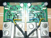
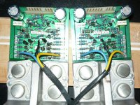
These are the resistors used for tuning the DC offset. What I did was replace one of them with a 50K pot. Then you can tune the offset to zero. Make sure you do it with your preamp connected and on. This design uses shunt feedback so the DC offset will vary depending on the input impedance.
Attachments
Being the 'one is good, two is better' kind of guy, I've picked up another pair of these and am hoping that they are proving to be worth the buck. Have they been stable and sounding great or have they caused no end of grief  . Dying to know before the new ones arrive and I start work on them,
TIA
Peter
. Dying to know before the new ones arrive and I start work on them,TIA
Peter
Late of me to chime in but the best place to put an offset adjustment pot would be in parallel with R18, R17 and ground. I suggest about a 1000 ohm pot. This is just the same as the balance pot circuit commonly seen on op-amp ICs.
Note that this pot in parallel with the R18 and R17 will increase the idle current through the output stage; for a 1K pot I suggest increasing R18 and R17 to 125 ohms or even more if you want to go on the safe side. If you feel like having around 20% more current, then leave them at 100 ohms but watch out because this amplifier really doesn't have any temperature compensation.
I've attached a quick example of what I'm explaining.
With this, the circuit can remain original or you can even put in matched resistor values for R7,R12,R8,R11 if you like (I would leave the originals personally).
This also means that if the pot should fail (wiper goes open or dirty), the amplifier will operate almost exactly as original with the exception of slightly higher idle current.
If anyone wants other suggestions I'm open to questions as I have one of these on the bench right now and have done some of my own reverse-engineering.
An externally hosted image should be here but it was not working when we last tested it.
Last edited:
as a variation on the previous suggestion, i have replaced the 2 120ohm resistors with 150ohms and put a 10k preset with resistors in each side (about 1k) to keep the reference voltage across the 25ohm resistors within the spec, so there is a small adjustment for 0v, i found keeping the dc to within around 50mv is most practical,
- Status
- This old topic is closed. If you want to reopen this topic, contact a moderator using the "Report Post" button.
- Home
- Amplifiers
- Solid State
- DC offset in Mission 777 amplifier