Hello!
On the diagram below I checked as diodes all transistors Q619 ... Q643 and they are ok but I always have either -48V or + 48V starting with the collector of Q619 and up to the base of Q640 / 641.
Something escapes me, Any idea?
I attached measurements, I think the problem passes "through" the input (IC601A), at different restarts DC offset appears or -40V, or + 40V as I noted above, with orange I put the voltages when DC offset occurs "-", with green when it goes on "+".
The voltages are lower compared to the normal ones because I supplied them ballasted by 2 lamps 48V / 5W (they light up poorly) because Q635 or Q636 heat up one by one (Ubc = close to supply voltage due DC offset), depending on how it goes, on + or -.
Something seems irregular with the voltages on the IC601A inputs / outputs.
Somehow it is unclear to me the role of IC601A combined with (Q602 & Q603)
Attachments
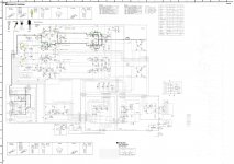
Your picture is too small to read.
The voltage at the collector of Q619 is sometimes -48 and sometimes +48? That doesn't make much sense - are you sure you are not swapping your meter leads?
When the voltage at Q619's collector is +48, what is the voltage at Q621's collector?
When the voltage at Q619's collector is -48, what is the voltage at Q621's collector?
Might want to look into using a simpler Dim Bulb Tester rather than your current 'ballasting' of the +/- power lines.
The voltage at the collector of Q619 is sometimes -48 and sometimes +48? - Yes, depends on how it start. Not swapping meter leads due black is fast on ground always.
When the voltage at Q619's collector is +48, what is the voltage at Q621's collector? - Q621's collector = Q621's emitter, that is marked on 2 colours, depends on how it start.
I have also a Dim Bulb Tester instead of power supply fuse but for me is more accurate to trace the ± idle currents.
I assume a problem in IC601A inputs / outputs or the same - input / driver transistors
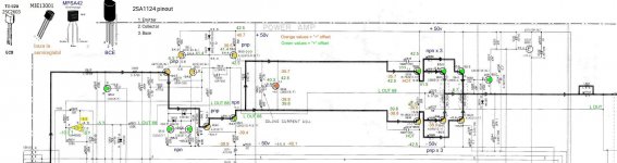
Your picture is still a bit hard to read but much better. In green, when your output offset is "+", I see you marked -5 on the non-inverting input to IC601A. With -5 volts on that pin, the other voltages are consistent with a properly functioning op-amp. But if your output is at +48 volts, that op amp pin should not be -5 volts.
Find R601, it should be near the opamp. When the output is at +48 volts measure and post the voltages on each end of R601.
Find R601, it should be near the opamp. When the output is at +48 volts measure and post the voltages on each end of R601.
The opamp looks to be a DC servo NOT input IC.
Yes, but if I understand the OP correctly, he has a high positive output offset but a -5 volt signal into the opamp. Somehow, that high + output is not making it to the opamp. The main amp itself is running open loop for DC.
Your picture is still a bit hard to read but much better....
Click the thumbnail. Hover. Click the "X" lower-left. It gets big enough.
Attachments
Q632, Q635, Q636 replaced with equivalents.
Q640, 641, Q642, Q643 replaced on the radiator but not connected on the board. If I connect them, the consumption increases and I have nothing to measure. If not connected, the emitter from Q635, Q636 becomes asymmetrical to the output rail. In this topology I think it must be 2 resistant as a load against the table.
All transistors Q602 .... Q651 checked as diodes, are ok.
The 48V / 5W bulbs - in series with ± 50V power supply, connected after electrolytes - light up very weakly but they also supply the functional channel (on the mainboard there is no power separation between the channel).
### As additional information, with R603 = 47K disconnected (IC601A seems ok now with R603 disconnected), the system starts at + 40V (bases Q635, Q636) so that after 20 seconds it starts to decrease rapidly (in about 3 seconds) until + 30V, then to quickly reverse the polarity (in about 2 seconds) decreasing to -40V, a value that remains constant for the rest of the measurements. Once stabilized at -40V, Q621 seems saturated.
I changed C616 = 100µF / 16V to 100µF / 100V, but no any changing in the above transient mode.
C603 47µV / 16V and C605 3.3µF / 50V are harder to reach, I haven't changed them at the moment. I don't see any other electrolytes to delay reversal.
The timing of the reversal is not related to protection relays triggering.
R673 = 220 ohms slightly discolored but at the nominal level.
Find R601, it should be near the opamp. When the output is at +48 volts measure and post the voltages on each end of R601.
All resistors around IC601 checked as ok, R603 = 47K disconnected but still transient mode with DC offset
Yes, but if I understand the OP correctly, he has a high positive output offset but a -5 volt signal into the opamp. Somehow, that high + output is not making it to the opamp. The main amp itself is running open loop for DC.
opamp isolated but still transient mode going to +40V... +30V...-40V
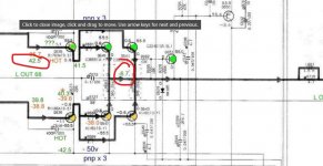
Green values = "+" offset (during first 20 seconds). Orange & pink values = "-" offset (after first 20 seconds, when values are "stabilised"). Q640, 641, Q642, Q643 replaced on the radiator but not connected on the board - as mentioned on post #10
Last edited:
With the output transistors disconnected, the amp is open loop and troubleshooting will be next to impossible.
You indicate that if you install the output transistors, the current draw increases too much.
Let's start by trying this: Connect your voltmeter between the base of Q635 (+ lead) and the base of Q636 (- lead). Power up and note the voltage between these bases. I would expect to see about 2.2 volts.
You indicate that if you install the output transistors, the current draw increases too much.
Let's start by trying this: Connect your voltmeter between the base of Q635 (+ lead) and the base of Q636 (- lead). Power up and note the voltage between these bases. I would expect to see about 2.2 volts.
Green values = "+" offset (during first 20 seconds). Orange & pink values = "-" offset (after first 20 seconds, when values are "stabilised"). Q640, 641, Q642, Q643 replaced on the radiator but not connected on the board - as mentioned on post #10
Right. So you have written 42.5 on the base, then 41.5 on the emitter followed by -6.7 at the output.
You can not have that difference in voltage between those points. If you have the 41.5 on the base of the outputs (as you show) then you must see around 41 volts on the emitter (and thus the output).
That is what you are showing.
# Ylli - I agree to you, for this particullary diagram Q635 & Q636 are "floating" without load.
As an answer: -35.4 - (-38.5) = 3.1 V, close enough to 2.2 but huge negative offset comparative to normal ±1.1V
If Q640 and Q642 will be connected due -36.9 on Q642 base, DC offset on output line will be -36.3 and protection will be on.
I suggest 1...2...3 kohm resistors instead of Q640 and Q642 to avoid "floating".
# Mooly - Please keep in your mind that green values are transient ones, may be not enough time to freeze a static point during measuremets. The orange & pink ones are "stabilised" - after first 20 seconds of transition.
It is my first time on such a "transient troubleshooting". It seems to be more difficult comparative to a static situation.
Last edited:
Also, all values, green, orange, pink - taken on open loop (Q640, 641, Q642, Q643 not connected)
Q621 is saturated after 20 seconds, it is important ...
Also, If you compare orange & pink, each day of measuremets shows slightly modified values and within one day measurements are not stabilised, altough I use a Fluke.
Also, If you compare orange & pink, each day of measuremets shows slightly modified values and within one day measurements are not stabilised, altough I use a Fluke.
I think after 20 seconds became a DC situation more than a transient one altough initially (first 20 seconds) it is a transition.
- Home
- Amplifiers
- Solid State
- DC offset ± 48V situation on Yamaha AX 750