The Mosfets should be locally decoupled - The Maplin schematic shows the caps close to the mosfets - Your stripboard loyout has the caps at the opposite end to the mosfets. I would suggest a pair of low ESR 100uF at least (without a small bipass cap)
Also note the Maplin Schematic shows an output inductor coil.
DC power supply leads can be twisted to improve things.
Gate resistors are in the right place close to the gates. Gate resistor values could be 680R - 1K. instead of 68R & 100R
Feedback resistor RF1 could be bipassed with a small capacitor (5pF) to reduce HF gain,
At least you only have one pair of Laterals to tame. You should try 16 at a time. 🙂
I used 68R on the P-channel and 100R on the n-channelmaybe i missed it - what values resistors are you using in series with the mosfet gates?
for this type of construction, it makes a significant difference.
And do you have a scope that can give you some idea of the frequency of oscillations to confirm it is the MOSFETs?
I am afraid to use bigger resistor values because then the gain margin is reduced and I would ruin the global stability. I had an inductor but got rid of him because it actually made the matters worse. I have also seen that many guitar amps don't use it. I should probably twist the power supply leads. I could also try the small cap in Rf1, but doesn't it ruin the phase?The Mosfets should be locally decoupled - The Maplin schematic shows the caps close to the mosfets - Your stripboard loyout has the caps at the opposite end to the mosfets. I would suggest a pair of low ESR 100uF at least (without a small bipass cap)
Also note the Maplin Schematic shows an output inductor coil.
DC power supply leads can be twisted to improve things.
Gate resistors are in the right place close to the gates. Gate resistor values could be 680R - 1K. instead of 68R & 100R
Feedback resistor RF1 could be bipassed with a small capacitor (5pF) to reduce HF gain,
At least you only have one pair of Laterals to tame. You should try 16 at a time. 🙂
UPDATE
All the suggestions were great. The MOSFETS do not appear to be oscillating. However the SMPS still remains the problem. I connected the RC filtering network, which indeed might be too far away from the MOSFETS. I enclosed the SMPS in an aluminum case, wrapped the supply cables in aluminum too, put everything on an aluminum sheet, grounded it and still this is what I get on the output.

I was using x10 probes and the division of the vertical axis is 20mV, so what you see is 200mV. The horizontal axis division is the smallest of the oscilloscope at 0.2μs. I count around 8 cycles in one division, so what you see is something around 40MHz.
This does not look like a MOSFET oscillation to me. It looks like switching noise...
I really don't know what else to do. I am not even sure how this passes through the filters. It was bigger before the filtering (actually before it was around a volt in amplitude). I guess I shouldn't have gotten that damnable SMPS

All the suggestions were great. The MOSFETS do not appear to be oscillating. However the SMPS still remains the problem. I connected the RC filtering network, which indeed might be too far away from the MOSFETS. I enclosed the SMPS in an aluminum case, wrapped the supply cables in aluminum too, put everything on an aluminum sheet, grounded it and still this is what I get on the output.
I was using x10 probes and the division of the vertical axis is 20mV, so what you see is 200mV. The horizontal axis division is the smallest of the oscilloscope at 0.2μs. I count around 8 cycles in one division, so what you see is something around 40MHz.
This does not look like a MOSFET oscillation to me. It looks like switching noise...
I really don't know what else to do. I am not even sure how this passes through the filters. It was bigger before the filtering (actually before it was around a volt in amplitude). I guess I shouldn't have gotten that damnable SMPS
SMPS would be around 20 to 60 mv ripple. Some very high current supplies might be 100 to 150 mv
which is considered " tolerable" by some for high current. Then again many well designed ones are still 30 to 60 mv
even at high current. No need to ask my opinion I pretty much cant stand the things.
There is lots of good advice in these post. Even though you have power supply decoupling caps.
they are on the other side of the board. There should be power supply decoupling caps very very close to the mosfets.
As far as the confusion with Gate resistors.
P channel and N channel mosfets have different gate capacitance
So at high frequency. one will be turning on or off faster. the other slower.
So there will be a lot of cross conduction and possible stability issue at high frequency.
2 ways to fix it are using higher gate value resistors for the N channel.
Since the p channel has almost 2x capacitance.
Or you add external capacitance compensation to the N channel
so it is somewhat more equal to the higher p channel capacitance.
What you can see is extremely high gate resistance values to " fix"
oscillation issues. When most the issue is higher p channel capacitance.
Good final fix is, using both methods. External capacitance for the n channel
being the main fix for cross conduction
Also with gate drive there is protection diodes in the mosfets.
But Exicon does also recommend external protection diodes.
I believe max voltage is around 14 volts so a good typical value
is around 10 to 12 volt Zener. Some go even lower for " hifi"
But as with musical instrument amplifiers your trying to get full power.
So I have seen very borderline protection around 11 to 13 volts.
Last edited:
I already used different value resistors, so that the MOSFET capacitances have the same RC constant. I have 100R in the n-channel and 68R in the p-channel. Maybe they are not adequate, but I still don't think the problem is instability because of the MOSFETs. I should try and make some space for a capacitor near the MOSFETS. I may also change the gate resistor values to a higher value and I will add a capacitor in the feedback resistor. If all these aren't enough I am pretty sure I should buy a torrodial transformer and make the thing work.SMPS would be around 20 to 60 mv ripple. Some very high current supplies might be 100 to 150 mv
which is considered " tolerable" by some for high current. Then again many well designed ones are still 30 to 60 mv
even at high current. No need to ask my opinion I pretty much cant stand the things.
There is lots of good advice in these post. Even though you have power supply decoupling caps.
they are on the other side of the board. There should be power supply decoupling caps very very close to the mosfets.
As far as the confusion with Gate resistors.
P channel and N channel mosfets have different gate capacitance
So at high frequency. one will be turning on or off faster. the other slower.
So there will be a lot of cross conduction and possible stability issue at high frequency.
2 ways to fix it are using higher gate value resistors for the N channel.
Since the p channel has almost 2x capacitance.
Or you add external capacitance compensation to the N channel
so it is somewhat more equal to the higher p channel capacitance.
What you can see is extremely high gate resistance values to " fix"
oscillation issues. When most the issue is higher p channel capacitance.
Good final fix is, using both methods. External capacitance for the n channel
being the main fix for cross conduction
Also with gate drive there is protection diodes in the mosfets.
But Exicon does also recommend external protection diodes.
I believe max voltage is around 14 volts so a good typical value
is around 10 to 12 volt Zener. Some go even lower for " hifi"
But as with musical instrument amplifiers your trying to get full power.
So I have seen very borderline protection around 11 to 13 volts.
As for the zener protection, I have checked the design in the simulation and it never has a gate-source voltage beyond 10V
Its good to protect gates, not only good practice. But high gain preamp, and sharp transients from musical instrument
can cause peaks.
Another attractive thing about mosfet, is zener protection is cheap easy current/ short circuit protection.
Another ok benefit to use source resistors, just not high value like .47 low value like .1
also makes bias current easy to measure.
I attach jpeg with good starting values for successful output stage including zobel.
amplifier input and output RF antenna. Simple RF filter on input like you added and zobel
help reduce RF interference.
And yes capacitor over feedback resistor not only helps stability, but you can bandwidth limit amplifier
for MI use ( musical instrument)
Attachments
The 40MHz oscillation is definitely a problem of the MOSFET power stage and does not relate to the smps. With my latest latFET build I observed oscillations close to 200MHz that could be fixed by local decoupling of the driver stage supply from output supplies.
Indeed it is an oscillation problem. I found the SMPS switching frequency to be around 28kHz and I also tested the SMPS output on the oscilloscope to find almost zero ripple and switching noise. It seems that it is a pretty decent one actually.The 40MHz oscillation is definitely a problem of the MOSFET power stage and does not relate to the smps. With my latest latFET build I observed oscillations close to 200MHz that could be fixed by local decoupling of the driver stage supply from output supplies.
I added some 0,1u caps directly to the MOSFET drains and the oscillation amplitude reduced dramatically to around 50mV. However it is still happening. What also helped is that I put everything on a grounded aluminum sheet.Its good to protect gates, not only good practice. But high gain preamp, and sharp transients from musical instrument
can cause peaks.
Another attractive thing about mosfet, is zener protection is cheap easy current/ short circuit protection.
Another ok benefit to use source resistors, just not high value like .47 low value like .1
also makes bias current easy to measure.
I attach jpeg with good starting values for successful output stage including zobel.
amplifier input and output RF antenna. Simple RF filter on input like you added and zobel
help reduce RF interference.
And yes capacitor over feedback resistor not only helps stability, but you can bandwidth limit amplifier
for MI use ( musical instrument)
As I said the oscillation is still there. And when I tried to add a small sine wave of 100mV in the input this is what I get
The oscillation is modulating the input. The output is the small waveform. It isn't even amplified! I tried increasing the input amplitude and I got this horrible result:
The PS was on its knees making a weird sound it makes when it draws lots of current and everything was heating up rapidly.
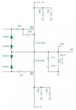
But I have all your suggestions in mind and I must go shopping for some capacitors. This is the schematic of the fixed design
1) C13 through C16 will be soldered as close to the drains as possible
2) increase the gate resistor values to 220R for both. I will balance them with C12 to increase the input capacitance of M1 to around 1,1nF, roughly the same as M2's.
3) C11 reduces HF gain and also increases the gain margin
4) I will try to find a proper power inductor to add to the output. I think 1μΗ is reasonable enough (?)
PS: I forgot the Zeners! I will add them too
I hope it will work this time. Any more suggestions before I proceed?
Also MASSIVE thanks for the feedback guys!
- Home
- Amplifiers
- Solid State
- DC measurements problems on original MOSFET class AB design