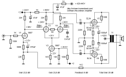
Have a set of quick questions on the DC Long Tail pair splitter.

- Just where the splitting happens? Across the 1M resistor?
- What is the function of that 0.22uf cap from grid to the ground? Would increasing it to 1uf make any impact on overall frequency spectrum? How critical is the quality of the cap used here? Cheap cap can do?
- Anode resistors need to be matched? In this instance one is 33k while the other is 39k. Purpose?
Last edited by a moderator:
2. Reduce noise, prevent unintended local feedback via the anode-grid capacitance.
3. Correct for the effect of the finite tail resistance and single-ended drive, I guess.
3. Correct for the effect of the finite tail resistance and single-ended drive, I guess.

Apparently I wasn't quite awake when I wrote post #2, as the correct answer to question 2 is that a long-tailed pair mainly responds to the difference between the grid voltages. Therefore, if you would just connect the grids together via a resistor without decoupling capacitor, the circuit simply wouldn't work.
This also means that the decoupling capacitor is about as critical or as uncritical as a normal AC coupling capacitor. Increasing its value increases the bass response further into the subsonic region. In a feedback amplifier, that may or may not cause motorboating. Leakage is also about as critical as for a normal AC coupling capacitor, so film capacitors are fine, but using electrolytic capacitors is asking for trouble.
This also means that the decoupling capacitor is about as critical or as uncritical as a normal AC coupling capacitor. Increasing its value increases the bass response further into the subsonic region. In a feedback amplifier, that may or may not cause motorboating. Leakage is also about as critical as for a normal AC coupling capacitor, so film capacitors are fine, but using electrolytic capacitors is asking for trouble.
Last edited:
1 and 3. The splitting happens in the upper valve of the long tailed pair, actually. Its anode and cathode currents are equal but in opposite directions. The other valve just redirects the AC component of the cathode current to the 39 kohm resistor. Some of that AC component actually flows through the tail resistor instead of through the other valve; to compensate for that, the bottom valve got a slightly higher anode resistor than the top valve (39 kohm instead of 33 kohm).
You drive signal to one grid; the other grid is at AC/Signal ground. 1Meg is the grids DC return, the capacitor keeps signal from driving the second grid.
The driven grid causes its cathode signal voltage to follow its grid signal voltage to about 1/2 gain, because that cathode drives its current into the other cathode, and the common cathode resistor. That "Robs" some of the first cathode's signal current, so the second cathode does not get all the first cathodes signal current.
The first cathode signal current causes its plate current to change, driving its plate load resistor.
But the second cathode's signal current is smaller, so the second plate current is smaller; we need a larger resistance second plate's load, so that we get equal gain (the first plate versus the second plate).
If the first grid moves positive versus the first cathode; its cathode moves up, but that means the second cathode moves up versus the second grid,
that is in opposite phase to the first grid to cathode signal voltage. That is where the phase inversion occurs, the direction of the first grid to cathode; versus the second cathode to grid signal voltage.
I use a CCS instead of the 15k common cathode resistor. The CCS does not "Rob" signal current from the first cathode, so the second cathode gets all of the first cathode's signal current. The cathode signal currents are equal now, so the plate signal currents are also equal (but they are in opposite phase).
Because the plate signal currents are now the same, matched plate load resistors are used (33k and 33k; or 39k and 39k).
Now you know why my phase inverters use CCS in the common cathode circuit; instead of a resistor to ground.
Last edited:
Solving for 1M+0.22uf gives 0.73Hz at -3dB. Is there more to it?Increasing its value increases the bass response further into the subsonic region. In a feedback amplifier, that may or may not cause motorboating. Leakage is also about as critical as for a normal AC coupling capacitor, so film capacitors are fine, but using electrolytic capacitors is asking for trouble.
Would that allow using a tube with mismatched halves ?Now you know why my phase inverters use CCS in the common cathode circuit; instead of a resistor to ground.
Solving for 1M+0.22uf gives 0.73Hz at -3dB. Is there more to it?
When you have a couple of first-order high-pass filters inside a feedback loop, you have to make sure they don't cause instability. You just calculated the open-loop corner frequency of one of them, the coupling capacitors you have at other locations and the magnetizing inductance of the output transformer (if any) are other high-pass filters in the loop. In the end, the loop gain has to cross the 0 dB line with a slope well below 40 dB/decade.
A coupled cathode phase inverter with a very good CCS and perfectly matched plate loads, will allow the plate swings to be equal amplitude and in opposite phase.
But your question is a real good one, because there IS a limit to the amount of the mismatch . . .
If one tube hogs most of the CCS current, the two plate DC voltages will be different, which means one plate will clip or run into the rails first.
Does that make sense?
But your question is a real good one, because there IS a limit to the amount of the mismatch . . .
If one tube hogs most of the CCS current, the two plate DC voltages will be different, which means one plate will clip or run into the rails first.
Does that make sense?
Makes eminent sense.
What would be good simple way to integrate a CCS in this situation? I do have a negative bias supply available.
What would be good simple way to integrate a CCS in this situation? I do have a negative bias supply available.
I went ahead a installed good quality modern 1uf film cap in that position. Originally it had 0.47uf vintage type cap.When you have a couple of first-order high-pass filters inside a feedback loop, you have to make sure they don't cause instability. You just calculated the open-loop corner frequency of one of them, the coupling capacitors you have at other locations and the magnetizing inductance of the output transformer (if any) are other high-pass filters in the loop. In the end, the loop gain has to cross the 0 dB line with a slope well below 40 dB/decade.
Sound actually got worse. Edginess on voices and diminished bass. What gives?
Selecting a CCS . . .
You do not need a negative supply for your CCS (the input stage plate voltage drives the inverter grid directly (DC). The inverter grid voltage, and the cathode voltage that is slightly higher than the grid voltage is more than enough to meet any CCS minimum burden voltage requirements.
Measure the voltage across the 15k cathode resisor.
Suppose it is 150V. 150V/15k = 10mA
Set your CCS current for 10mA
Suppose the swing on the inverter grid is + / - 20V. The parallel cathode voltage swing is 1/2 that, + 10 / - 10V.
That would mean the CCS would have to work properly from 150V - 10V (140V) to 150V + 10V (160V).
The CCS must dissipate 160V x 0.010A = 1.5 Watts
Heat sink the CCS if it needs it.
Take out the 15k, and replace with the CCS.
Replace the 33k and 39k plate resistors with extremely well matched pair of resistors (33k pair, or 39k pair).
Done
Wrt to CCS I am leaning towards the idea of having all tube arrangement that would lend itself well to p2p wiring. Any pitfalls ? How is the attached schematic as 1st PP build? I work in heavy engineering and have a healthy respect for HV.
That ECC88 seems to be passing 150vdc. In safe zone?
That ECC88 seems to be passing 150vdc. In safe zone?
Attachments
Triodes are not good for CCS. The anode current changes with the anode voltage given a bias point. If you want to use tubes, then a pentode will be best. Maybe one of the dual triode/pentodes like ECF82 would be a good fit to replace V1 and V2.
Edit: ECF82 or 80 not a good fit for the 14.6 mA in your schematic. Will need something beefier, with a flat line around that current.
Edit: ECF82 or 80 not a good fit for the 14.6 mA in your schematic. Will need something beefier, with a flat line around that current.
Last edited:
Screen current is often the limiting factor in using little pentodes for CCS tails. I like the 6JW8 as it has a nice triode in there, but it’s pentode is lightweight for 15 mA. Great at 3-5 mA. I was looking at 6LF8 as the next step up. Looks like it would work here too. There is always the ones with the video output pentodes when all else fails. Their plate charcateristic is not as flat, but when you stick a large enough cathode resistor in there it flattens way out. Same is true of triodes, but it takes a larger resistor (and more voltage drop) to do it. And then you quickly run out of voltage headroom. Sharp cutoff pentodes do well with as little as 50V on the plate, provided you keep an eye on screen current. You end up needing one big enough for at least 3X the tail current that you target, and use vg1 (ie, cathode resistor) to back it off. That combination raises output impedance and forces ig2 down.
I have used the PCL84 in an experimental build, it works pretty well, and the triode has plenty of gain. But the ECL84 is close to unobtanium.
Edit: Spoke too soon, plenty of NOS on ebay.
EF184 seems like a good option:

Edit: Spoke too soon, plenty of NOS on ebay.
EF184 seems like a good option:
Last edited:
One of those with the video output pentode in it. Never seen the curves on the 6DX8 triode, although basic characteristics look like the 12AT7 64 mu triode that floating around all over the TV tube world. More familiar with the 6KV8, which has that triode, and has a pentode capable of driving 1000 feet of cable as a k-follower or making a 5 to 7 watt push pull amp out of a pair. Nice general workhorse. If you can the 6LY8 it has that same pentode with a true 12AX7 100 mu triode in it.
I have a couple of ECL82, EF80 and EF86 at hand.
All in used condition. Can we have something around these?
All in used condition. Can we have something around these?
- Home
- Amplifiers
- Tubes / Valves
- DC Long Tail pair splitter question