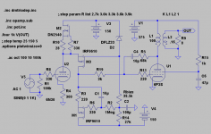
A few months ago Rod Coleman presented this concept:
http://www.diyaudio.com/forums/tubes-valves/153318-shunt-cascode-power-valve-driver.html
By adding a negative supply and a "gyrator" we can DC-connect to the output tube. Bias is adjusted by Rbias😉.
This one is conceptual so don´t bother discussing detail solutions as which MOSFET/BJT, tube etc. to choose. So by using Rods CCS and voltagesource the result might be better.
The first issue(if it is an issue), as I can see it, is that bias is partly dependant on tube drift. No big thing as its the voltagedrop over R3 that will change at upstart(no current through the tube) giving 4-5V to much biasvoltage. Ie if the tube drifts 5mA we get in the ballpark of 1V biasdrift.
Then second issue, that is common to more Schades, is the interaction between L1, C1,and C4. To avoid a low frequency "bump", great care must be taken. A high primary inductance is always better.
Attachments
Last edited:
What did I say about discussing details? Avoid that please🙂.
But please comment the circuit instead.
For you to learn, it is called "uppkomling" in Swedish.
But please comment the circuit instead.
For you to learn, it is called "uppkomling" in Swedish.
Last edited:
Hi Lars,
Maybe use some DC feedback to the U2 cathode to stabilize the U1 grid Op. point.
If you use a P chan. part for M2, Rod used ZVP0545A, you can eliminate C4 from the Schade network by returning the feedback resistor to M2's source/resistor. This will also improve the PSRR by separating B+ rail references from ground references by the Hi-Z current source in between. Some DC current sampling resistance (capped over) in the L1 to B+ connection could then provide DC servoing of the the bias thru the Schade feedback to M2 source. M3 folded cascode is not needed then either if some DC shift is provided (cap or resistor network to - rail, Uh, except a cap there will break the DC servo of bias, so a resistor network is called for). The U2 triode can then work in triode mode also, not being loaded down by the Schade feedback.
Don
Last edited:
Hey Don,
Thanks, will try some of your ideas when I get home from work. Whatever solution I choose another P-channel is a good idea as CCS. Also TBD is wether to use a BJT or FET as M3.
About C4 I think it can be eliminated/shorted as is. The drawback is 6mA more current through the OPT and off course then, 6mA more through the gyrator. Don´t know if it as any more drawbacks though.
A few months ago Rod Coleman presented this concept:
http://www.diyaudio.com/forums/tubes-valves/153318-shunt-cascode-power-valve-driver.html
By adding a negative supply and a "gyrator" we can DC-connect to the output tube. Bias is adjusted by Rbias😉.
This one is conceptual so don´t bother discussing detail solutions as which MOSFET/BJT, tube etc. to choose. So by using Rods CCS and voltagesource the result might be better.
The first issue(if it is an issue), as I can see it, is that bias is partly dependant on tube drift. No big thing as its the voltagedrop over R3 that will change at upstart(no current through the tube) giving 4-5V to much biasvoltage. Ie if the tube drifts 5mA we get in the ballpark of 1V biasdrift.
Then second issue, that is common to more Schades, is the interaction between L1, C1,and C4. To avoid a low frequency "bump", great care must be taken. A high primary inductance is always better.
Hey Lars,
This is clever. I have been playing with current mirrors doing something similar.
What's the effective anode load impedance on your driver triode? It looks like you are applying current feedback to a cascoded triode with a fixed anode voltage. Why not a pentode as you have advocated in the past?
I haven't found that driver drift is a huge issue, depending on the DC slope of the output tube; The value of R3 just needs to be "large enough" relative to 1/gfs of the MOSFET. Have you tuned this in spice?
The LF instability should be manageable by making the input signal roll off before the feedback signal, as freq is decreased. These should both probably be above the OPT roll-off. Even with DC feedback there is the OPT Lpri issue.
BTW, I have come to regard C1 and R2 in effect the same as RC coupling to a source follower, the only difference being the significance if 1/gfs.
At the end of the day, what problem is being solved here?
Cheers,
Michael
Hey Don,
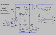
The idea of returning the Schade feedback to the top of the CCS ie source of M2 can not work, but I anyway rearrange the schematic for a P-channel.
Hey Michael,
Not much is gained, just a variation on a theme that I am fond of🙂.
These few things:
It´s cheaper than D3a.
You don´t need couplingcaps.
You get fixed-bias for free.
Attachments
Last edited:
hello Lars,
Glad you are having some fun with that cascode circuit!
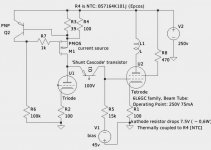
For bias stability, I was thinking about something like this for any of the shunt cascode variants.
The (outline) schematic shows the idea. Add a little cathode resistance (7 - 10V bias). when the heat from that kathode resistor is just right, you can sense it with an NTC to adjust the current source. No electrical contact, no capacitor sound!
I don't know if the circuit can really drive a Schade network... perhaps a source follower would be a good idea.
Glad you are having some fun with that cascode circuit!
For bias stability, I was thinking about something like this for any of the shunt cascode variants.
The (outline) schematic shows the idea. Add a little cathode resistance (7 - 10V bias). when the heat from that kathode resistor is just right, you can sense it with an NTC to adjust the current source. No electrical contact, no capacitor sound!
I don't know if the circuit can really drive a Schade network... perhaps a source follower would be a good idea.
Attachments
Hey Rod,
Interesting idea, must try to digest that one!
The cascode works about in the same way as a pentode so it will work like a charm together with distortion-cancellation. Running 20mA through it makes work as any high-Gm pentode like D3a. Actually it sims better.....
Interesting idea, must try to digest that one!
I don't know if the circuit can really drive a Schade network...
The cascode works about in the same way as a pentode so it will work like a charm together with distortion-cancellation. Running 20mA through it makes work as any high-Gm pentode like D3a. Actually it sims better.....
"The idea of returning the Schade feedback to the top of the CCS ie source of M2 can not work, "
You mean that U2 holds its voltage gain too well? I was hoping that R4 in U2's cathode would make it have enough output Z to have some effect. If the M3 cascode is present, then it should have even more effect. Too bad one cannot return the Schade feedback to M3's gate, but wrong phase polarity. Could go with a pentode for U2 I guess.
You mean that U2 holds its voltage gain too well? I was hoping that R4 in U2's cathode would make it have enough output Z to have some effect. If the M3 cascode is present, then it should have even more effect. Too bad one cannot return the Schade feedback to M3's gate, but wrong phase polarity. Could go with a pentode for U2 I guess.
You guys worry way too much bout a high pentode impedance.
You only need constant impedance (very low works just fine too).
No problem: cathode, emitter, or source follower near zero impedance.
No problem: cascode, pentode, sand, or hybrid near infinate impedance.
Only you probably do not want: curvy mid impedance triode plate.
Except of course as the end result of the Schade transformation.
If a triode existed with a TOTALLY flat plate impedance, you could
drive a Schade with it I suppose. The impedance becomes part of
the voltage divider. That such division of Schade feedback retains
constant proportion is the function you don't want to sabotage.
Tack an emitter follower onto the end of this contraption, you got
a winner for Schading the next stage. The same could be said for
emitter followers equalizing the output impedances after a folded
Concertina (see the other thread of the same topic, why two???)
Last edited:
Hey kenpeter,
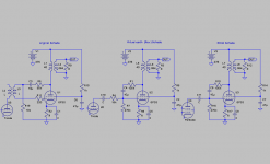
Your´e so right about drivers if we remember that there are three different types of Schade-configurations, or trioderizors. Will draw them when I come home.
Still, in my view, the best are pentodes or cascodes as distortion-cancellation have the greatest effect.
Your´e so right about drivers if we remember that there are three different types of Schade-configurations, or trioderizors. Will draw them when I come home.
Still, in my view, the best are pentodes or cascodes as distortion-cancellation have the greatest effect.
Last edited:
Here thay are with their drivers. The third can of course use a cascode but NOT a triode for good results.
Attachments
Last edited:
You are forgetting the one where the cathode sits atop an output winding.
I recall AR doing some sort of ugprade thing with a Dynaco. The 4ohm Tap
became the common, and cathodes sit upon 0 and 16...
I recall AR doing some sort of ugprade thing with a Dynaco. The 4ohm Tap
became the common, and cathodes sit upon 0 and 16...
- Status
- Not open for further replies.
- Home
- Amplifiers
- Tubes / Valves
- DC hybrid folded-cascode for Schade