I want to give this TubeCAD phono stage a whirl, and I plan to use 12.6 VDC for the heaters. Can someone post a circuit for a regulated DC supply, perhaps using an LT1085 or similar? Assume I will purchase a low voltage PT to dedicate to this use.
Cheers!
Cheers!
Attachments
I have this board, schematic is in the listing. I just use a 12V SMPS for mine though ")
LT1083CP 7.5A Tube Amp Filament Voltage Regulator Adjustable Power Supply Kits | eBay
LT1083CP 7.5A Tube Amp Filament Voltage Regulator Adjustable Power Supply Kits | eBay
Last edited:
I've used this at lower current than what you'll need but it's rated to 2.5A:
H-PS-1 low-voltage regulator
It is a LT1085 IIRC.
H-PS-1 low-voltage regulator
It is a LT1085 IIRC.
euro₂₁;5564773 said:IMHO you win earlier a lottery prize, than finds four same -identical- half tubes. :—(
Twin triode's uniformity usually not best than 20 percent… except rare tubes.
I have some Siemens CCa (twin triode) tubes, four of them has 5 percent uniformity of halves.
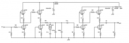
I think the idea is that the use of 3 tubes, 2 for the first stage, all triodes in parallel, but each driven into conduction by its own capacitor bypassed cathode bias resistor averages out the individual section characteristics substantially.
Thus, if you package 2 sets of these three-tube preamplifier stages in a single box, you get stereo with much better gain matching than normally one typically achieves with single-triodes-per-section designs.
At least that's my thought.
Because clearly its not about “sharing the load” between the 4 sections
… power wise.
Same goes for the 12AU7s. Being lower mu, they're also going to have closer operating characteristics, all in all. Fewer sections in parallel “needed” to tighten up the left-right channel gain.
All THAT said, it certainly kind of falls off the page: why not just have a set of 5 kΩ-in-series-with–50 kΩ potentiometers for small trim.
Just saying,
GoatGuy
I am cheap, especially when it pays off. Just use 12 V. fixed regulator(s). That's well within 5% of nominal on the low side. FWIW, a favorite design of mine is Schottky diode "full wave" voltage doubled 6.3 VAC into a 7812.
Quite a few "vintage" designs "starve" the heaters, for (IIRC) noise reasons.
Quite a few "vintage" designs "starve" the heaters, for (IIRC) noise reasons.
You can read about the circuit here: The Tube CAD Journal: Parrell tubes
This is what John Broskie had to say about the high capacitance:
The usual disadvantage of using many tubes in parallel is the greatly increased input capacitance, but in a phono preamp this capacitance works in our favor. Phono cartridges like to be loaded by capacitance, as the capcitor's declining impedance with increasing frequency helps to damp the cartridge's high frequency resonances. And the second gain stage's increased input capacitance only helps to complete the passive equalization network's own internal need for a final shunting capacitance.
Is this off the mark?
> in a phono preamp this capacitance works in our favor.
I think John got over-enthused here. There is an "optimum" loading. This was conventionally designed around 100pFd in 3 feet of cable and ~~100pFd into a high-Mu triode, something a bit over 200pFd.
There's likely to be 340pFd (1.7pFd*4*50) just in the triodes. Add to that the cable, it's pretty heavy for some carts (not a problem for others).
The two cartridges I use mainly are a Denon 103R and an AT95E (much different - I know!). How would those handle the high capacitance?
I'm new to phono design, so I'm not dead-set on the posted TubeCAD circuit. I chose it because I have a lot of high quality 12A_7 tubes, and because the 300V B+ makes it easier to drop into my current work-in-progress line stage preamp. My PT has a 500V secondary (+250 / -250) and after CLCLC I'm right around 300V B+. I'd prefer a tube based design with passive RIAA, but I'm open to suggestions.
I'm new to phono design, so I'm not dead-set on the posted TubeCAD circuit. I chose it because I have a lot of high quality 12A_7 tubes, and because the 300V B+ makes it easier to drop into my current work-in-progress line stage preamp. My PT has a 500V secondary (+250 / -250) and after CLCLC I'm right around 300V B+. I'd prefer a tube based design with passive RIAA, but I'm open to suggestions.
Last edited:
Try Broskie's boards, maybe?
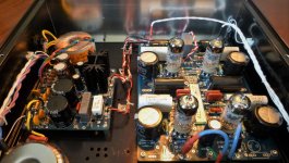
I'm not a fan of old or new 12AX7s. They seem to start noisy or go noisy with depressing regularity. See attached for picture of Tubecad Tetra and PS-3. Regulated B+ not needed with the Tetra. I built mine with 12AT7s, TungSol reissues. It sounds decent, to me anyway. Just bought the Tetra board and stuffed it with my own parts. Chassis is eBay from China. No heavy-duty metal working required just hole drilling. Use Broskie's AC switch )New AC Selector Switch) for ON/OFF and all you need is a 9mm hole, unlike the one I used that required some outside machining.
Cheers, Steve
Attachments
Cartridge loading; Morgan Jones advises against a single ECC83 in the 3rd edition of his book due to high capacitive loading. That is, unless you are prepared to run short phono cables or you use an older Ortofon or Shure cartridge.
Instead he promotes the use of 6922/E88CC (or even up to 3x in parallel).
OTOH - The RCA RIAA (Refined by Eli Duttman - search this forum) uses the 12AX7 and appears to have many happy users. I would also recommend to take a look at Valewizard.co.uk. Merlin has a published design and offer a PCB for a RIAA, including calculated component values for a variety of 12A?7 type valves and corresponding calculated capacitive loads (again, including 12AX7).
I am about to order his PCB. It seems is also prepared for PCC types as well as the ECC/12A style heaters.
Denon 103R is a low output MC cartridge so you'll need an additional low noise transistor stage (valves are too noisy). Something like KSA 1381 would be a good choice for noise.
Or a step up transformer?
- Status
- This old topic is closed. If you want to reopen this topic, contact a moderator using the "Report Post" button.
- Home
- Amplifiers
- Tubes / Valves
- DC Heaters for Phono Preamp