1. I can't use the chasis to dissipate heat, what size heatsink would you suggest using?
2. My 6.3V windings (which I will wire in series for this) actually measure ~7V, meaning 14V in series. Do you think that a simple voltage divider (i.e. two resistors) after the bridge diodes is a good idea to bring this down to 12.6V?
You need to do a little modeling. I assume that your 14V is with the transformer unloaded. The whole point of PSUD is to predict the actual operating conditions. It works. Use it.
Second, your DC voltage will be about 1.4 times the AC voltage - which PSUD will accurately estimate - assuming that you enter the proper values for your transformer and other components.
Third, if you are using a regulator, then a couple of extra volts are not a problem. In fact it's probably helpful.
Finally, once you model the voltage to the regulator, you can calculate the voltage drop across the Mosfet and multiply that by filament current. That gives the power dissipated in the Mosfet. From that you can size your heatsink. The specifications for the sink are often shown as temperature rise for a given power - for instance, 2W/20 degrees C. I'd keep the temperature rise less than 40 degrees, 20 degrees is better . Remember too, that these specs. are relative to the starting temperature, and in free air. If you locate the sink in a warm environment, or with poor circulation, or both, you must go larger.
Sheldon
Pardon the dumb question, but when I model the supply to the regulator, can I simply assume the current draw is equivalent to that in an unregulated supply? (i.e. 0.15A x number of tubes)?
thx
Pardon the dumb question, but when I model the supply to the regulator, can I simply assume the current draw is equivalent to that in an unregulated supply? (i.e. 0.15A x number of tubes)?
Absolutely.
Here is an example how in one of my garage made prototypes I bolted MOSFETs and Shottky diodes for all regulators on an aluminium angle attached to chassis.
http://wavebourn.com/forum/download.php?id=112&f=7
You can use diodes to drop a little voltage as well. Schottkys for just a little and normal diodes for a little more.
Btw, biasing the heaters to a positive voltage, 20-60volts, will prevent any hum from entereing your circuit.
One thing I've started to use is a soft start circuit on my heaters. Having read 'Getting the Most Out of Your Tubes' (download from P.Millet's awesome site), I did a little check on the inrush current into cold heaters.
I took 3 Sovtek and one JJ E88CCs and set my lab supply to 6.3volts and max current to 1amp. On all the Sovteks the current peaked just above 900ma, and the JJ actually wanted more than 1amp! When I set the current limit to 350mA the heaters took some 20 seconds to reach 6volts.
So I either include a current limiting device, or feed the heaters with a CCS.
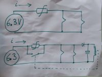
Here is a very simple soft start:
It uses a varistor, I think 30ohm but anything from 5 to 50ohms will probably work. When the heaters and the varistor is cold, the voltage is mostly over the varistor. The varistor's resistance goes down as it heats up, and more current goes to the heaters. Eventually the voltage over the heaters approaches 6volts and the rectifier clicks in and shorts the varistor. The time on my latest creation with 3 preamp tubes and two 6L6s is about 15-20seconds.
More advanced soft starts are of course nice, but why bother when this simple solution works.
Btw, biasing the heaters to a positive voltage, 20-60volts, will prevent any hum from entereing your circuit.
One thing I've started to use is a soft start circuit on my heaters. Having read 'Getting the Most Out of Your Tubes' (download from P.Millet's awesome site), I did a little check on the inrush current into cold heaters.
I took 3 Sovtek and one JJ E88CCs and set my lab supply to 6.3volts and max current to 1amp. On all the Sovteks the current peaked just above 900ma, and the JJ actually wanted more than 1amp! When I set the current limit to 350mA the heaters took some 20 seconds to reach 6volts.
So I either include a current limiting device, or feed the heaters with a CCS.
Here is a very simple soft start:
It uses a varistor, I think 30ohm but anything from 5 to 50ohms will probably work. When the heaters and the varistor is cold, the voltage is mostly over the varistor. The varistor's resistance goes down as it heats up, and more current goes to the heaters. Eventually the voltage over the heaters approaches 6volts and the rectifier clicks in and shorts the varistor. The time on my latest creation with 3 preamp tubes and two 6L6s is about 15-20seconds.
More advanced soft starts are of course nice, but why bother when this simple solution works.
Attachments
You can use diodes to drop a little voltage as well. Schottkys for just a little and normal diodes for a little more.
Yes, but it would be constant voltage drop so differences in mains voltage will cause more difference of filament voltage. Like contra-regulator. Also, diodes will add switching interferences.
Speaking of varistors, it is a good point.
You can use diodes to drop a little voltage as well. Schottkys for just a little and normal diodes for a little more.
Btw, biasing the heaters to a positive voltage, 20-60volts, will prevent any hum from entereing your circuit.
One thing I've started to use is a soft start circuit on my heaters. Having read 'Getting the Most Out of Your Tubes' (download from P.Millet's awesome site), I did a little check on the inrush current into cold heaters.
I took 3 Sovtek and one JJ E88CCs and set my lab supply to 6.3volts and max current to 1amp. On all the Sovteks the current peaked just above 900ma, and the JJ actually wanted more than 1amp! When I set the current limit to 350mA the heaters took some 20 seconds to reach 6volts.
So I either include a current limiting device, or feed the heaters with a CCS.
Here is a very simple soft start:
It uses a varistor, I think 30ohm but anything from 5 to 50ohms will probably work. When the heaters and the varistor is cold, the voltage is mostly over the varistor. The varistor's resistance goes down as it heats up, and more current goes to the heaters. Eventually the voltage over the heaters approaches 6volts and the rectifier clicks in and shorts the varistor. The time on my latest creation with 3 preamp tubes and two 6L6s is about 15-20seconds.
More advanced soft starts are of course nice, but why bother when this simple solution works.
Nice, thanks! Will add the varistor to the design. BTW, what is CCS?
Also, all this information is making me wonder if I should mod my integrated amp...it's an old Rogers Cadet III with AC heating by default which suffers from a slight (but noticeable on very quiet recordings) hum...do you reckon changing heater supply to DC (and even more so regulated) would benefit it?
CCS stands for Constant Current Source.
Regarding the Rogers amp; personally, going to DC filaments would be low on my list. There are many possible sources of hum, and a quiet amp with AC on the filaments (for indirectly heated cathodes) is not that difficult.
Sheldon
wavebourne - a quick question if you have a minute:
I have some bridge rectifiers (all in one) lying around, can I use them instead of the four diodes in the bridge? The factsheet for the component is this one:
http://docs-europe.origin.electrocomponents.com/webdocs/0dcf/0900766b80dcfb02.pdf
and it's the GBL10 (4A - 1kV) variant I have.
thx,
Nikos
I have some bridge rectifiers (all in one) lying around, can I use them instead of the four diodes in the bridge? The factsheet for the component is this one:
http://docs-europe.origin.electrocomponents.com/webdocs/0dcf/0900766b80dcfb02.pdf
and it's the GBL10 (4A - 1kV) variant I have.
thx,
Nikos
wavebourne - a quick question if you have a minute:
I have some bridge rectifiers (all in one) lying around, can I use them instead of the four diodes in the bridge? The factsheet for the component is this one:
http://docs-europe.origin.electrocomponents.com/webdocs/0dcf/0900766b80dcfb02.pdf
and it's the GBL10 (4A - 1kV) variant I have.
Hi Nikos;
you may use them, but voltage margin will be 1V less that with 1N5822 Shottky diodes I used. Think of voltage variations in power outlets.
for the regulator, Fee it from the last C in the above CRC. Use the common 7805. It is a 5V reg but it you connect the center lead to ground via a diode it will become a 6.3 V reglator that can deliver 1A of curent.
Which way does the cathode of the diode face? Toward the regulator or toward ground? Dumb question, I know. I'd guess the cathode (stripe) needs to face toward ground, so that 0.7V appears on the middle pin of the 7805. But I'm not sure I understand exactly how this is working.
[edit] Sorry for the interruption.
Thanks...
--
Last edited:
Hi Nikos;
you may use them, but voltage margin will be 1V less that with 1N5822 Shottky diodes I used. Think of voltage variations in power outlets.
Thanks, don't really understand but I'll stick to individual diode bridge for the heaters. For educational purposes, what does "voltage margin" mean?
N
Thanks, don't really understand but I'll stick to individual diode bridge for the heaters. For educational purposes, what does "voltage margin" mean?
It is not about individual diodes, but about ordinary Silicon diodes VS Silicon diodes with Shottky barrier. Shottky barrier lowers voltage drop on forward conducting diodes.
Suppose, you have 12.6V AC under the nominal load. 12.6V is an effective voltage that would produce 12.6 Watt on 12.6 Ohm resistance. Amplitude voltage is square root of 2 higher. Diodes in a bridge conduct by pairs, that means you have each half of period 2 diodes in series conducting the current. Voltage drop on open diodes causes less of rectified voltage. If to use Shottky diodes the result will be about 17 Volt, if to use ordinary Silicone diodes it will be 16 Volt.
Voltage regulator needs voltage margin to regulate voltage. It works such a way so voltage drop on the pass element (MOSET in our case) is always automatically adjusted to have the same voltage on output, no matter how high is a voltage on it's input. But there are some limits: particularly, it can't be less than output voltage. If it is less, a voltage stabilizer can't work anymore, and output voltage will be below an input one, unregulated.
AC voltage in power outlet is not 120V stable (240 V in Europe, 100 V in Japan, 220 V in Russia, and so on). It is variable, depends on load that varies during the day and day to day. That means, a voltage stabilizer needs some margin of input voltage to work all the time, during the day, and day to day.
Also, you have to think of ripples: a filter capacitor once charged by open diodes is discharging through the load. That causes ripples. Dips of ripples must be above some minimal voltage needed for the pass element to work above output voltage that you need to get at the output.
Do you hear me now? 😉
Thanks, this is very clear! I am getting 14V out of my secondary, so the higher voltage drop of the bog-standard bridge is a blessing in disguise. In fact, 19.9 - 2 = 17.9V out of the bridge, ~1V higher than your PSU using 12.6V and shottky's - presumably the MOSFET will be happy with this?
Again, for purely encyclopaedic purposes, what would the highest voltage input the MOSFET would accept and what would happen if this was exceeded?
Thanks!
Again, for purely encyclopaedic purposes, what would the highest voltage input the MOSFET would accept and what would happen if this was exceeded?
Thanks!
A first, avalanche break-up may happen, and MOSFET start conducting as a Zener diode. Second, it may be overheated and damaged by heat.
I used 2SK1388 MOSFET, you may check it's max values there: http://www.datasheetcatalog.org/datasheet/fuji/2SK1388.pdf
30 Volt, 60 Watt.
60 Watt means when it is 25 degrees Celsius, but actually it always will be hotter, depending on heatsink used. You may find max power depending on temperature on the SOA graph (Safe Operation Area) in the datasheet (it is called Allowable Power Dissipation graph in this particular datasheet).
Hello Wavebourne (or anyone else for that matter), I was wondering if I could ask for some help with the regulated supply:
http://wavebourn.com/forum/download.php?id=116&f=7
This is my second attempt to build this (first one ended up with me burning the transistors as I'd used normal diodes instead of zeners for D5 ad D6).
I've now re-built it with new transistors, and 12V 0.5W (lowest power I could get my hands on) zeners for D5 and D6. It works, in the sense that it gives regulated DC, but sadly the voltage is 6.3V! I have absolutely no idea what I could be doing wrong! Can anyone please help?
Thanks!
Nikos
Well, it should be roughly 13V. Are you sure your "300V" is really 300V and you got your component values right ? This circuit should work with quite wide range of values of resistors as long as your D5 is indeed 12V and both transistors are operating properly.
Anyway, if it was me I'd be using integrated regulator (LM350 and the like) in place of discrete solution; it is likely to give better results with lower circuit complexity for smaller loads and with equal complexity for larger loads (additional pass transistor needed).
Anyway, if it was me I'd be using integrated regulator (LM350 and the like) in place of discrete solution; it is likely to give better results with lower circuit complexity for smaller loads and with equal complexity for larger loads (additional pass transistor needed).
Actually, my 300V turned out to be zero - I'd forgotten to "link" the neutral of my HT and heaters' supplies!
I am getting a wonderfully constant 12.8V and the smile on my face is touching my ears! I'll be hooking it up to my pre-amp later tonight and doing the first test. I'm so excited!
Once again, thanks to everyone, particularly Wavebourne. Will report first impressions as soon.
Nikos
I am getting a wonderfully constant 12.8V and the smile on my face is touching my ears! I'll be hooking it up to my pre-amp later tonight and doing the first test. I'm so excited!
Once again, thanks to everyone, particularly Wavebourne. Will report first impressions as soon.
Nikos
- Status
- Not open for further replies.
- Home
- Amplifiers
- Tubes / Valves
- DC heater supply for phono pre