Hi there,
Having just figured out what to do with the HT supply, I'd like to pick people's brains on some concerns I have about the heater supply for a phono pre-amp I am building.
First of all, the pre-amp uses 3 ECC83s and 2 ECC82s. Moreover, in the future I will be re-building it (after I make sure I like the sound), to have 2 the 3 ECC83 section twice, this into resistors and into a tweaked version of the 2 ECC82 one (adding some feedback), to make a 2 channel phono mixer. Ultimately, I will therefore be running 6 ECC83s and 2 ECC82s from this supply.
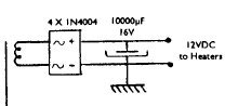
The original schematic for the heater supply (attached below) calls for a 10 V secondary, into a bridge rectifier and smoothed by a large-ish capacitor of 10mF to give 12v DC.
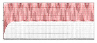
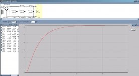
My first concern is with the original supply. I put everything into Duncan Amps' PSUDII into a load, and got the graph of the voltage across the load attached below. It shows a pretty hefty voltage ripple (3.7 min, 10.9 max), and a max voltage which is significantly less than 12v. Am I doing something wrong, does the original design have problems or is this all ok?
More relevant to my specific case is the fact that my transformer doesn't have a 10 or 12 V secondary, but has two 6.3v (they are actually more like 7v as it happens) ones. Now, obviously one can wire the heaters of the ECC83s and ECC82s in parallel with a 6.3v supply. The problem is that when I tried to simulate a similar design to the original in PSUDII, but with my trafo's parameters, I got a min-max of 0.3V - 6.8v. Is this acceptable?
Final question relates to the current draw. As ~6.3v operation means double current draw by the heaters (.3A instead of .15A under 12v), I am worried that I may be running into limits there, given 5 or 8 valves. Does the fact that I have a second 6-7V primary mean I can run two separate PSUs and therefore double my current draw capacity, or do the two depend on one another? If ambivalent, is there a way to check?
Thanks,
Nikos
Having just figured out what to do with the HT supply, I'd like to pick people's brains on some concerns I have about the heater supply for a phono pre-amp I am building.
First of all, the pre-amp uses 3 ECC83s and 2 ECC82s. Moreover, in the future I will be re-building it (after I make sure I like the sound), to have 2 the 3 ECC83 section twice, this into resistors and into a tweaked version of the 2 ECC82 one (adding some feedback), to make a 2 channel phono mixer. Ultimately, I will therefore be running 6 ECC83s and 2 ECC82s from this supply.
The original schematic for the heater supply (attached below) calls for a 10 V secondary, into a bridge rectifier and smoothed by a large-ish capacitor of 10mF to give 12v DC.
My first concern is with the original supply. I put everything into Duncan Amps' PSUDII into a load, and got the graph of the voltage across the load attached below. It shows a pretty hefty voltage ripple (3.7 min, 10.9 max), and a max voltage which is significantly less than 12v. Am I doing something wrong, does the original design have problems or is this all ok?
More relevant to my specific case is the fact that my transformer doesn't have a 10 or 12 V secondary, but has two 6.3v (they are actually more like 7v as it happens) ones. Now, obviously one can wire the heaters of the ECC83s and ECC82s in parallel with a 6.3v supply. The problem is that when I tried to simulate a similar design to the original in PSUDII, but with my trafo's parameters, I got a min-max of 0.3V - 6.8v. Is this acceptable?
Final question relates to the current draw. As ~6.3v operation means double current draw by the heaters (.3A instead of .15A under 12v), I am worried that I may be running into limits there, given 5 or 8 valves. Does the fact that I have a second 6-7V primary mean I can run two separate PSUs and therefore double my current draw capacity, or do the two depend on one another? If ambivalent, is there a way to check?
Thanks,
Nikos
Attachments
Last edited:
You can connect the two 6,3VAC windings in series, obtaining 12,6VAC.
8 ECC's at 12,6VDC will draw about 1,2A. Therefore the 1N400x won't do: you need some heaftier diodes.
What value of capacitor and load have you used in your PSUD simulations?
Valve amplifiers by Morgan Jones has some extensive information on regulation, routing and common-mode noise filtering for heaters. And as you move further with the hobby you will find it has a lot more of interesting information!
You should also consider limiting the turn-on surge current through the diodes. As you have drawn it, the only limit is the residual resistance in the circuit, both too low and uncontrolled.
Further, I would suggest that, since you apparently want to do this to reduce residual hum pickup, that you filter the supply better than just one huge capacitor. You need to have cleaner power, else the advantage of dc is lost.
Further, I would suggest that, since you apparently want to do this to reduce residual hum pickup, that you filter the supply better than just one huge capacitor. You need to have cleaner power, else the advantage of dc is lost.
You can connect the two 6,3VAC windings in series, obtaining 12,6VAC.
8 ECC's at 12,6VDC will draw about 1,2A. Therefore the 1N400x won't do: you need some heaftier diodes.
What value of capacitor and load have you used in your PSUD simulations?
Valve amplifiers by Morgan Jones has some extensive information on regulation, routing and common-mode noise filtering for heaters. And as you move further with the hobby you will find it has a lot more of interesting information!
Thanks, first of all (so that I don't screw this up), by connecting the two windings in series you presumably mean connecting the "live" of winding A to the "neutral" of B and then using the "live" of winding B and the neutral of winding A - correct?
Capacitor was 9.4mF (haven't found a 10mF so I'll use 2 4.7mF ones) and load was constant current of 1.5A (5 x 0.3A).
What diodes would you recommend using for the bridge?
I'll see if I can get a copy of the book to flick through - building this with a separate PSU unit in part because I am interested in future improvements (of course also to improve hum).
You should also consider limiting the turn-on surge current through the diodes. As you have drawn it, the only limit is the residual resistance in the circuit, both too low and uncontrolled.
Further, I would suggest that, since you apparently want to do this to reduce residual hum pickup, that you filter the supply better than just one huge capacitor. You need to have cleaner power, else the advantage of dc is lost.
first question: how do you limit the turn-on surge current?
Second question: what filter would you add? All attempts I made (in my ignorance) to add things in PSUDII came up with weird results...
thanks!
Last edited:
You can limit surge current with a resistor in series with the winding. You can improve filtering with a filter choke or resistor and a second capacitor. You can kill both birds with one stone by putting a resistor or choke between the rectifier and the capacitor.
You might read some theory on transformer-rectifier power supplies. When you add components, you lower the output voltage. This actually may be good if you have too much output for the tubes. The idea is to hit 6.3V when all the tubes are lit and the mains voltage is at nominal. Best to operate tubes within 5% of 6.3 and in no case more than 10%. Higher will shorten life and lower can affect performance.
You might read some theory on transformer-rectifier power supplies. When you add components, you lower the output voltage. This actually may be good if you have too much output for the tubes. The idea is to hit 6.3V when all the tubes are lit and the mains voltage is at nominal. Best to operate tubes within 5% of 6.3 and in no case more than 10%. Higher will shorten life and lower can affect performance.
I've read some of the replies and I'd suggest something different and I think better. This is after all a preamp you like it dead quiet. I think the best way to go is a regulated DC supply. Ideally I'd build it as a 12.6V regulated supply but you don't have the right transformaer for that. If you have space in the chassis and can affors the extra $20 cost. Buy a second transformer for the hears. A 24 volt transformers will do and they are not expensive. But if you can't add another transformer then build a regulated 6.3V DC supply
For either voltage the first thing is to run the AC into a big bridge. Don't mess with in4007 diodes, just buy a bridge that is rated at 2X the number of amps you need.
Run that into a large filter cap. Then a resister and a second cap. In other words your basic CRC filter. Start with a 100R then adjust it later.
Now for the regulator, Fee it from the last C in the above CRC. Use the common 7805. It is a 5V reg but it you connect the center lead to ground via a diode it will become a 6.3 V reglator that can deliver 1A of curent. Use as many 7805 chips as you need. Each regulator will supply current to a few tubes. You will need bypass caps on both in and out of each 7805
It is more conventional to use one big regulator with a power transistor but a small handful of 7805 chips is easy to build and understand and to get right. Not only that but the big supply will go "poof" and let put some smoke if something goes wrong. The 7805 will simply shut down because it has thermal and over current protection built-in
As a last step after the tubes are all installed and glowing. Adjust that 100R resistor to be as large as you can make it while still having 9V in the inputs o the 7805 chips
If you can add that second tranformer then build a 12.6V DC supply the same way. It will be easier because it will need only 1/2 the current.
OK if you don't want to mess withj a regulated supply at least use a CRC supply because (1) final voltage adjustment can be done be fine tunning the "R" and you get lower ripple for the same total amount of C.
Last edited:
Before you buy stuff and heat up the soldering iron, let's play in PSUD some more. Show the PSUD schematic window. Or show the screen. Then we can make specific suggestions and ask intelligent questions.
Sheldon
Sheldon
I totally agree with the regulated supply concept. Greinacher ("full wave") voltage double 6.3 VAC/5 A. using 2X Schottky diodes rated for at least 10 A. continuous and at least 25 PIV. Use 2X 15000 μF. 'lytics in the doubler stack. The 10 μF. originally mentioned is a using a water pistol to shoot an elephant. Joules/uF. stored is very small at low voltages. This is NOT a 300 V. B+ supply. Follow the doubler stack with several well heatsinked 7812 3 terminal regulators. As 12 V. (on the dot) is within 5% of nominal, on the low side, the tubes' heaters will be in "Hog Heaven".
Thanks again for the suggestions and tips.
Chris, I will read up into the regulated option over the next weekend. Do you think I could combine this with Erik's earlier suggestion of wiring the two 6.3V taps in series to get 12V? Not really an issue of money but would rather not have a huge box for the power supply, unless there are clear advantages in a separate transformer.
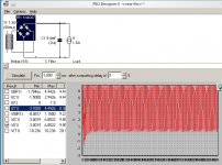
Sheldon, thanks for the offer to look at it, I am attaching a screen-grab. Running this on Kubuntu with Wine rather than actual windows, so I couldn't really get PSUDII to export pdfs, sorry if it doesn't look too good.
For your reference, parameters for the transformer were 7V and 7A (these were the readings I got roughly when I tested it), cap is 9.4mF (2X 4,700uF, as I couldn't find 10,000uF). Load is constant current of 1.5A (5X0.3A for each ECC8x).
Graph in red is the voltage across the load, which (after stabilising) fluctuates between 0.336V and 6.562V.
Chris, I will read up into the regulated option over the next weekend. Do you think I could combine this with Erik's earlier suggestion of wiring the two 6.3V taps in series to get 12V? Not really an issue of money but would rather not have a huge box for the power supply, unless there are clear advantages in a separate transformer.
Sheldon, thanks for the offer to look at it, I am attaching a screen-grab. Running this on Kubuntu with Wine rather than actual windows, so I couldn't really get PSUDII to export pdfs, sorry if it doesn't look too good.
For your reference, parameters for the transformer were 7V and 7A (these were the readings I got roughly when I tested it), cap is 9.4mF (2X 4,700uF, as I couldn't find 10,000uF). Load is constant current of 1.5A (5X0.3A for each ECC8x).
Graph in red is the voltage across the load, which (after stabilising) fluctuates between 0.336V and 6.562V.
Attachments
Ok. First thing, as Eli suggests, is to use a Schottky diode rated for your load. His suggestions are fine for specifications.
Try 1N5822 for your model. Also try 20mOhm for the series resistance of the cap. It will be nowhere near 2 Ohm for any reasonable 10mF cap. Then work from there. Even if you use active regulation (which I also recommend), you need a good model of the supply before the regulator. I would use the low dropout versions. No need to waste power.
If you want, you can do a CRC, with something like 0.2R resistors. A couple of RC sections will knock down ripple considerably. I wouldn't worry about turn on surge at this point, and I certainly would not add resistance before the first C. Do some modeling first.
Sheldon
Attachments
Ok. First thing, as Eli suggests, is to use a Schottky diode rated for your load. His suggestions are fine for specifications.
Try 1N5822 for your model. Also try 20mOhm for the series resistance of the cap. It will be nowhere near 2 Ohm for any reasonable 10mF cap. Then work from there. Even if you use active regulation (which I also recommend), you need a good model of the supply before the regulator. I would use the low dropout versions. No need to waste power.
If you want, you can do a CRC, with something like 0.2R resistors. A couple of RC sections will knock down ripple considerably. I wouldn't worry about turn on surge at this point, and I certainly would not add resistance before the first C. Do some modeling first.
Sheldon
Thanks - it was the erroneous resistance of the cap that was causing the dodgy results.
Thanks for all the tips everyone, I will try this first with an unregulated CRCRC supply (9.4mF per cap and 17R for the resistors seemed to do the trick in the simulation so I'll start with that) and will look into a regulated supply when I start making the final version of the pre-amp. Will undoubtedly come back for help then. 😀
Nikos
17R for the resistors seemed to do the trick in the simulation
You mean R17, or 0.17R, no? And Wavebourn knows his stuff, so if you can get suitable parts, I'd go that way instead of multiple three terminal regs..
Sheldon
17 Ohm not 0.17 Ohm - my transformer measured ~7V, so to get 6.3 after rectification and smoothing I needed to drop the voltage a bit (schematic & graph attached).
Regarding the Wavebourn design, I think I will probably go for it in the final version, so if I could as a few things (and please excuse my ignorance):
Are the two AC "nodes" at a 12.6V difference between them or compared to ground and out of phase (in other words ~25 between them). If the former, can I just "series" the two 6.3V secondaries I have to do this?
Another thing I wanted to check on the design is the +300v. The transformer I am using, in addition to the two ~7V secondaries has two more secondaries, one giving 260-270V @80mA and one giving a little more than 300, if memory serves. I was going to use the 260-270 one for HT, can I use the remaining tap to supply the +300v shown in the schematic?
Finally, what diodes should I use?
Attachments
17 Ohm not 0.17 Ohm
Ohms law (V=IR)says no way. At 1.5 amps you will drop 25.5 volts over a 17 ohm resistor. Check your current source. It's probably set up as a step function and you are looking at 0 current.
Are the two AC "nodes" at a 12.6V difference between them or compared to ground and out of phase (in other words ~25 between them). If the former, can I just "series" the two 6.3V secondaries I have to do this?
The former, and yes.
Another thing I wanted to check on the design is the +300v. The transformer I am using, in addition to the two ~7V secondaries has two more secondaries, one giving 260-270V @80mA and one giving a little more than 300, if memory serves. I was going to use the 260-270 one for HT, can I use the remaining tap to supply the +300v shown in the schematic?
In Wavebourn's design, the HV supply and R2 just form a current source to bias Q2. The voltage is not critical. Just use your filtered B+.
17 Ohm not 0.17 Ohm - my transformer measured ~7V, so to get 6.3 after rectification and smoothing I needed to drop the voltage a bit (schematic & graph attached).
Regarding the Wavebourn design, I think I will probably go for it in the final version, so if I could as a few things (and please excuse my ignorance):
Are the two AC "nodes" at a 12.6V difference between them or compared to ground and out of phase (in other words ~25 between them). If the former, can I just "series" the two 6.3V secondaries I have to do this?
Another thing I wanted to check on the design is the +300v. The transformer I am using, in addition to the two ~7V secondaries has two more secondaries, one giving 260-270V @80mA and one giving a little more than 300, if memory serves. I was going to use the 260-270 one for HT, can I use the remaining tap to supply the +300v shown in the schematic?
Finally, what diodes should I use?
If you are doing 12V, your current will be halved, to 0.75A. In that case, 1N5821, or 5822, will be fine. If you go with 6V, I think the 3A part would still be OK, but you could step up to something like 80SQ045.
Sheldon
Last edited:
17 Ohm not 0.17 Ohm - my transformer measured ~7V, so to get 6.3 after rectification and smoothing I needed to drop the voltage a bit (schematic & graph attached).
Regarding the Wavebourn design, I think I will probably go for it in the final version, so if I could as a few things (and please excuse my ignorance):
Are the two AC "nodes" at a 12.6V difference between them or compared to ground and out of phase (in other words ~25 between them). If the former, can I just "series" the two 6.3V secondaries I have to do this?
Another thing I wanted to check on the design is the +300v. The transformer I am using, in addition to the two ~7V secondaries has two more secondaries, one giving 260-270V @80mA and one giving a little more than 300, if memory serves. I was going to use the 260-270 one for HT, can I use the remaining tap to supply the +300v shown in the schematic?
Finally, what diodes should I use?
I used 12.6V winding, floating. In another amp I used 2 windings 6.3V in series (they also powered 6L6GC and EM80 filaments).
+300V means 1 MA current source. If it is slightly less or slightly more does not matter. Using B+ and a high resistance resistor is better than using a CCS and a small voltage source, such a way the regulator works down to almost zero voltage drop on MOSFET. Also, I don't care of number of tubes connected to the output (except 12.6V AC current capability), when MOSFET has good thermal contact with chassis.
Diodes I used 5822, they must be Shottky diodes. You may use as well 3-leg Shottky diodes from computer power supplies, I did that in an amp that needed more of current than 5822 want.
Edit: I see Sheldon answered all questions already. Keep mine for redundancy. 😀
Last edited:
17 Ohm not 0.17 Ohm - my transformer measured ~7V, so to get 6.3 after rectification and smoothing I needed to drop the voltage a bit (schematic & graph attached).
When I tried this I got the same result. It seems to be that PSUD itself programmed the current source to step down to 100mA. maybe a weird bug of some kind because I know I didn't enter a current step and didn't save/reload the file or anything...
Uncheck the current step and try again!
Needless to say, I've had it happen a number of times where a step function was entered by the program. I check routinely now.
Sheldon
Sheldon
I used 12.6V winding, floating. In another amp I used 2 windings 6.3V in series (they also powered 6L6GC and EM80 filaments).
+300V means 1 MA current source. If it is slightly less or slightly more does not matter. Using B+ and a high resistance resistor is better than using a CCS and a small voltage source, such a way the regulator works down to almost zero voltage drop on MOSFET. Also, I don't care of number of tubes connected to the output (except 12.6V AC current capability), when MOSFET has good thermal contact with chassis.
Hi there,
A couple of questions:
1. I can't use the chasis to dissipate heat, what size heatsink would you suggest using?
2. My 6.3V windings (which I will wire in series for this) actually measure ~7V, meaning 14V in series. Do you think that a simple voltage divider (i.e. two resistors) after the bridge diodes is a good idea to bring this down to 12.6V?
Thanks,
Nikos
- Status
- Not open for further replies.
- Home
- Amplifiers
- Tubes / Valves
- DC heater supply for phono pre