Sure, but TO-220 schottky rectifiers best, eg Fairchild or ONSEMI 10A/45V. drop only about 0.4v each.
MBR1045PBF Vishay Semiconductors Schottky (Diodes & Rectifiers)
MBR1045PBF Vishay Semiconductors Schottky (Diodes & Rectifiers)
So in theory i might be able to run 8 volt heaters from a 6.3vac tap...
It is what I did in my first Tower hybrid amp, for 8AL9 tubes.
well I made a supply using CRC... the caps are both 16v 10,000uf (actually smaller than my B+ 47uf caps). The resistor is a 5W 2 ohm. I am getting 6.2 volts. This is not incorporated into my amplifier yet as I just used a breadboard. You guys see any problem with this heater supply?
Is that 6.2VDC with no load? Or did you have the tube filament connected to load the heater supply?
If it's 6.2VDC under load, then that should be fine.
Hello,
Pete Millett has been at it again. Take a look at this http://www.diyaudio.com/forums/tubes-valves/170028-dc-filament-supply-boards.html . This new Little PCB makes heater power supplies Fast and easy. Thank you Pete.
DT
All Just for Fun!
Pete Millett has been at it again. Take a look at this http://www.diyaudio.com/forums/tubes-valves/170028-dc-filament-supply-boards.html . This new Little PCB makes heater power supplies Fast and easy. Thank you Pete.
DT
All Just for Fun!
Well I have completely built my circuit. I am not hearing or getting much of 60 hz hum on my scope. The CRC 10,000 cap to 2ohm resistor to 10,000 cap worked great.
I am now only having trouble with 120hz buzz. I'm pretty darn sure its not ripple but grounding issues. I have the circuit star grounded following the valve wizards article. I have the signals from each stage going to their local B+ cap node and then I have the nodes daisy-chained from cap to cap and back to the bridge rectifier ground and then to the chassis at the transformer base screw. I also have the DC heater bridge grounded at the transformer base screw. There are no center taps.
1) Would it be better to not daisy chain the local nodes and just run them straight to the star ground point with individual wires?
2) Is there a better place to ground the heater rectifier?
A perfect common mode choke acts like a balun, so each wire gets half the hum voltage. The hum current is unchanged. So hum caused by magnetic induction is unchanged; hum caused by leakage may reduce a little.Sometimes high current common mode chokes can be liberated from dead PC power supplies. These don't offer much help in reducing hum, but they kill the diode switching noise.
And that has what to do with grounding?
let me rephrase the questions..
1) Is it ok that I am daisychaining the nodes together?
2) Is it ok that If I ground the heater rectifier to the B+ rectifier ground and then to chassis?
let me rephrase the questions..
1) Is it ok that I am daisychaining the nodes together?
2) Is it ok that If I ground the heater rectifier to the B+ rectifier ground and then to chassis?
Also I am getting absolutely no noise when the gain of this preamp is at a level that is not clipping (or moderately clipping). Its actually lower than my fender amplifier on clean. Maybe there is no such thing as a quiet tube guitar overdrive?
Scribbles
Bob,
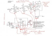
I scribbled on the original hotbox schematic you posted to show STAR GROUNDING.
It may be of some use to you - or maybe not!!!
Notes:
Drawing an extra 1mA 'ish from power supply node B for the +50V DC heater reference - might need to drop the 22K/2W to 18K or 15K
Added grid stop to the cathode follower, cathode followers are notorious for parasitic oscillation without the grid stopper AND the very high frequency oscillation is sometimes noticed as additional hum (coz you stress the power supply more).
Dropped the cathode follower idle current to something a 12AX7 can manage for a decent lifetime.
I would also add a 470nF/630V across the first 33uF/450V in the power supply.
Sitting the 6.3V DC supply on +50V like this WILL improve the sound and also reduces the heater to cathode voltage for the cathode follower which MAY also help reduce hum.
When thinking about grounding - make sure there are NO power supply return currents flowing down the same piece of wire as the signal returns, for example see the first stage, signal return current and power supply bypass capacitor currents flow thru' separate wires back to the star earth.
Cheers,
Ian
Bob,
I scribbled on the original hotbox schematic you posted to show STAR GROUNDING.
It may be of some use to you - or maybe not!!!
Notes:
Drawing an extra 1mA 'ish from power supply node B for the +50V DC heater reference - might need to drop the 22K/2W to 18K or 15K
Added grid stop to the cathode follower, cathode followers are notorious for parasitic oscillation without the grid stopper AND the very high frequency oscillation is sometimes noticed as additional hum (coz you stress the power supply more).
Dropped the cathode follower idle current to something a 12AX7 can manage for a decent lifetime.
I would also add a 470nF/630V across the first 33uF/450V in the power supply.
Sitting the 6.3V DC supply on +50V like this WILL improve the sound and also reduces the heater to cathode voltage for the cathode follower which MAY also help reduce hum.
When thinking about grounding - make sure there are NO power supply return currents flowing down the same piece of wire as the signal returns, for example see the first stage, signal return current and power supply bypass capacitor currents flow thru' separate wires back to the star earth.
Cheers,
Ian
Attachments
Last edited:
It is best to keep charging pulses away from the star ground. So connect rectifier -ve directly to reservoir capacitor -ve, then run a single wire from there to the star ground. This wire then only carries DC plus the ripple current to the first smoother - much less trouble than the charging pulses.
Do something similar for the heater rectifier. You can also twist the +ve and -ve wires from the rectifier together to get some cancellation of magnetic fields from the charging pulses.
The separate rectifier grounds should meet only at the star point, otherwise noise from one circuit can get injected into another.
Hello All,
Amateur here asking amateur questions. I'm trying to build a DC heater supply for two 6BH6 preamp tubes. I have a 6 volt 420 MA transformer. (I've read that this may be too small.) I used Schottkys for the rectifier and came up with 8.3vdc. But when I tried the LM317 regulator I could only get about 4.3 volts to the heaters under load. So I removed the regulator and just hooked it up direct to the heaters to see what I would end up with. When wired direct under load I have 6.95 vdc. I've also read that heater supply voltage needs to be within +/- 5%. Between 5.98 and 6.61volts. My mains voltage runs high, 125-126 volts so in the interest of portability I would probably want to stay near the upper limit, about 6.5 volts. The first two caps in the filter are 1500uf/50 volt, the second cap is a 100uf/100volt. At this point there is no resistor, so its just a CC filter. I need to drop about half a volt. So if I install a .001 ohm resistor .5/420 = .0011 between the caps would that work?
Also, when wiring the heaters do you run power to one side of the filaments (in parallel) and then the other side to ground?
Thanks for any help you could provide.
Under the "Never mind" heading. Do you measure the voltage between the input to the heater (Pin 3 on a 6BH6) and ground? Or across the heater pins, between 3 and 4? It just occurred to me to measure across the heater. When I just did this I got, believe it or not, 6.35 volts. Am I done? It seems mains variation would still be between the +/- 5%. Is this wishful thinking? How can this screw up?
Wow a tube with 150ma heater, guess ive been using big tubes for too long. So thats 300ma total. So you should be within spec. Yes you measure 3-4. Personaly i would go low, not high. So id shoot for 6-6.3, not 6.3 to 6.6.
What im guessing is that its not a 6 volt 420ma transformer, its a 5 volt under load or its not a 420 and your overloading it and causing a large voltage drop. Since your running ubber low current, i would just do it the easy what and pop some ultra cheap 4001 diodes in series. .7 volts drop per diode guaranteed regardless of whats going on with your mains power.
In theory, 6.3 vac becomes 9 volts, then drops down 1.4 volts with the rec, then pop in 2 more diodes in series and you should hit your mark.
Its really hard to run a lm317 with a 6 volt transformer. You cant get the voltage high enough to start regulating.
I double checked Antek rates the transformer for 6 volts at 420 MA. And the 6BH6 tubes really only draw .150 amps on the heaters per tube. My mains are high so almost anywhere else the circuit will be somewhere just below 6.3 volts. The 6BH6 was designed for applications with ow heater draw in AC/DC receivers. I think I read somewhere it was designed for battery operated shortwave radios. The only tubes on this circuit are the two preamp tubes and they are really tiny.
Use This transformer TRANSFORMER 16VCT/1.6A OR 8V/3.2A | AllElectronics.com in Full Wave CT (2 diodes). There will be plenty of voltage for a LM317 / LM1085 to stay in regulation.Wow a tube with 150ma heater, guess ive been using big tubes for too long. So thats 300ma total. So you should be within spec. Yes you measure 3-4. Personaly i would go low, not high. So id shoot for 6-6.3, not 6.3 to 6.6.
What im guessing is that its not a 6 volt 420ma transformer, its a 5 volt under load or its not a 420 and your overloading it and causing a large voltage drop. Since your running ubber low current, i would just do it the easy what and pop some ultra cheap 4001 diodes in series. .7 volts drop per diode guaranteed regardless of whats going on with your mains power.
In theory, 6.3 vac becomes 9 volts, then drops down 1.4 volts with the rec, then pop in 2 more diodes in series and you should hit your mark.
Its really hard to run a lm317 with a 6 volt transformer. You cant get the voltage high enough to start regulating.
DT
Yes, but my question is if I have 6.35 volts without a regulator. Do I really need to change anything?
antek 6 run alittle low in the voltage(common complaint with tubers). Your tubes are rated for 6.3 so if your getting 6.35 id say your dead on. If hum has been eliminated then id say your gold.
The whole goal is just to eliminate hum, so anyway you can do that is a good one. Still odd that a 6vac +rec+cap+load=6.35v
The whole goal is just to eliminate hum, so anyway you can do that is a good one. Still odd that a 6vac +rec+cap+load=6.35v
I am looking for a way to run DC heaters off a 6.3v supply. In this schematic there is only a large cap after a bridge rectifier.
http://schematicheaven.com/effects/matchless_hotbox_overdrive.pdf
Thanks
The bridge is drawn wrong !!!!!
antek 6 run alittle low in the voltage(common complaint with tubers). Your tubes are rated for 6.3 so if your getting 6.35 id say your dead on. If hum has been eliminated then id say your gold.
The whole goal is just to eliminate hum, so anyway you can do that is a good one. Still odd that a 6vac +rec+cap+load=6.35v
Hello,
If you are happy leave it alone.
Not odd at all. At low load (VA) the transformer is putting out more than 6 volts AC.
One down side of no regulator is that you are dependent on the AC voltage delivered to your meter. When the voltage droops on a hot afternoon in August so will your heater voltage.
DT
- Status
- Not open for further replies.
- Home
- Amplifiers
- Tubes / Valves
- DC heater large cap