benefits of R4?
Can somebody please explain to me which benefits R4 adds to the DC supply? On Pete's website he only talks about increasing the value of R4 when using higher voltages, but nothing about why this current drawing resistor benefits the supply.
The schematics can be found here: Regulated DC filament supply
It acts as a load on the DC bus, and therefore indirectly on the filament transformer serving the PCB. Depending on the regulation of the transformer, you can adjust R4 to pull more/less power. This will have small effects on the average DC bus, and will also increase ripple a bit.
Other than those small effects and the ability to discharge the bus when powered off, R4 isn't all that critical to the operation of the circuit.
Other than those small effects and the ability to discharge the bus when powered off, R4 isn't all that critical to the operation of the circuit.
Can somebody please explain to me which benefits R4 adds to the DC supply? On Pete's website he only talks about increasing the value of R4 when using higher voltages, but nothing about why this current drawing resistor benefits the supply.
The schematics can be found here: Regulated DC filament supply
R4 is a "bleeder" resister. Its just is to discharge the capacitors when the power is turned off. It is mainly there for safety so that the high voltage goes away when you turn the unit off.
Imagine how dangerous it would be if there was a lethal voltage present even when the unit was unplugged from the AC mains outlet. We ALWAYS install this resister and choose a resistance that is a compromise to drain the caps in a reasonable time but not to waste so much power in operation
When I am building an amplifier I plut in a low value "bleeder" resister. usually a big ceramic power resistor in parallel to the normal small bleeder so the volts go to zero nearly instanly. This makes working on the amp safer. Then after the amp works, I remove the low value paralleled resister.
CHose the value of R4 so at your voltage only about 0.1 watts is used. (remember Ohm's law and I squared R)
Right, so I installed a 750R resistor instead of the suggested 121R resistor. This would use a little bit more then 0.1 Watts.
Another question. The amplifier uses cathode bias, so there is already a high quality 100uF capacitor (C6) there. Should I omit C7 and C2 from the supply?
Another question. The amplifier uses cathode bias, so there is already a high quality 100uF capacitor (C6) there. Should I omit C7 and C2 from the supply?
Attachments
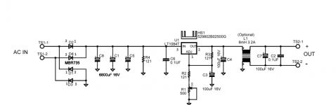
C2 is supposed to work in conjunction with the common mode choke; ideally it is located physically close to the choke. Not sure what the dielectric is for this design, but a quality film or ceramic is beneficial. C7 could be removed.
You need a "floating" filament supply. Not one peppered with ground symbols. That will short-out your cathode bias and burn the tube quick.
No. The "ground symbols" are the common negative rail of the voltage regulator. This is NOT anywhere connected to the amplifier ground. The supply is floating, unless you connect the transformer secondary to something other than the supply.
Pete
Pete
- Status
- Not open for further replies.
- Home
- Amplifiers
- Tubes / Valves
- DC Filament supply boards