Hi, im building an amplifier power supply, in my case a dc to dc converter that takes 24v dc and outputs +/-60vdc. It works on the basic push pull converter topology.

My converter has gone great so far but i need to upgrade the transformer so that it can handle higher current. This will be done by increasing windings/ wire gauge, while retaining primary:secondary turns ratio of my current transformer. In order to add more turns, a larger core is needed, which is why i am not using the current core.
Looking into easily available toroid cores in the uk, mostly on eBay, i see alot of fair-rite cores.
I believe i need a core with a high permeability in the 2000-3000nH range, preferably with a diameter somewhere less than 45mm.
The 77 material range looks good?
Any opinions on the 5977002701 core? It is the one I'm thinking of going with.
Would love other core suggestions that are easily available in uk.
Last edited:

The main formula for this type of converter is n=Vf/(4*B*F*Ae).
n is the minimal number of turns for the primary (or each half-primary depending on the configuration), B is the peak induction tolerated by the core, F is the frequency of operation and Ae is the effective cross-section of the core.
With all the unit in SI, you get the required number of turns directly.
In your case, the published data uses "monkey units", mostly CGS-derived, meaning you have some conversions to do.
To take your example, and supposing your topology is inductive PP, each half-winding sees 24V during the conduction phase, meaning n= 24/(4*0.35*50e3*0.78e-4). 0.35 is the induction in tesla, derived from the 100°C curve in the datasheet (3500 gauss is 0.35 T), and I have assumed an operating frequency of 50kHz.
Thus, n=4.4 and in practice 5 (that's the minimum, 6 would be safer).
Note that Epcos or Ferroxcube have much higher performance materials, capable of operating close to 0.5T at high frequencies, high temperature and low losses (and they don't use fancy units in their data)
Thanks for the calculations, 6 turns sounds good - could you perhaps link me to the datasheet you found, i have struggled to find one with the graph for peak induction.
Also, how do i decide on other factors like the wire gauge or number of strands, after the number of primary turns required has been found.
Surely permeability is important if i want to keep current draw reasonable at idle load.
Also, how do i decide on other factors like the wire gauge or number of strands, after the number of primary turns required has been found.
Surely permeability is important if i want to keep current draw reasonable at idle load.
The datasheet for the toroid is here: https://fair-rite.com/product/toroids-5977002701/
And the induction can be inferred from the B-H graph in the "material" tab:

You can see that the blue curves level up at 3500 gauss, indicating a substantial loss of permeability.
Note that the magnetizing current has practically no impact on the active current consumption, idle or otherwise, because it is recycled one way or another.
For the wire gauge, you can use a relatively large current density, between 5 and 10A/mm², because the transformer is relatively small, and has a high area to volume ratio.
Chose a diameter of strand low enough to make the skin effect negligible at the operating frequency (there are online calculators for that).
Note that the skin effect will be influenced by other factors, like the windings layout, therefore it is prudent to be generous if you have room enough in the aperture of the toroid
And the induction can be inferred from the B-H graph in the "material" tab:
You can see that the blue curves level up at 3500 gauss, indicating a substantial loss of permeability.
Note that the magnetizing current has practically no impact on the active current consumption, idle or otherwise, because it is recycled one way or another.
For the wire gauge, you can use a relatively large current density, between 5 and 10A/mm², because the transformer is relatively small, and has a high area to volume ratio.
Chose a diameter of strand low enough to make the skin effect negligible at the operating frequency (there are online calculators for that).
Note that the skin effect will be influenced by other factors, like the windings layout, therefore it is prudent to be generous if you have room enough in the aperture of the toroid
One more point: I based the design example on reasonable assumptions and values, but I have no idea about the actual values. If the frequency is not 50kHz or the topology is different, the number of turns will differ too.
You have to plug your own values into the formula
You have to plug your own values into the formula
Of course, my circuit has potentiometers so i can easily change the frequency to 50khz or any value up to 100khz. I will likely use a different core as the one i was looking at is not really that available, i will definitely take a look into Epcos or Ferroxcube
Just to bore and confuse here are some sums.
An SMPS, if it is not resonant, applies square wave voltages to the primary of your core. Elvee gives an equation for Sine Wave excitation which will introduce an error.
Your core has a primary magnetizing inductance, Lpri. The change in current through that inductance is,
dIpri = Vin.Ton/Lpri
For a push-pull convertor the transformer frequency, Ftran, is half of the oscillator frequency, Fosc, you might need to check my head. So 100KHz, Fosc, gives you 50KHz, Ftran. The on time, Ton, is a maximum of 10uS. That might have bent your head the wrong way because I worry too much.
The dI gives you the peak to peak current in the transformer primary and results in a peak to peak flux density in the core.
It is that peak to peak flux density, or rather half of it, that you would use in the power loss curves. That's down to the way that the graphs in the datasheets are scaled.
Lpri = Uo.Ue.Npri^2/Ae.Le
Uo is permeability of free space, 4PIe-7, Ue is effective permeability of the core, Ae is the effective area of the core and Le is the effective length of the core.
We can simplify that one by using the specific inductance of the core,
AL = Uo.Ue/Ae.Le
Lpri = AL.Npri^2
substituting,
dIpri = Vin.Ton/AL.Npri^2
However we want the flux excursion, dB.
dB = Uo.Ue.Npri.dIpri/Le
Again we, almost, substitute for AL but don't forget the Ae,
dB = AL.Npri.dIpri/Ae
rearrange,
dIpri = dB.Ae/AL.Npri
then equate,
dB.Ae/AL.Npri = Vin.Ton/AL.Npri^2
AL cancels,
dB.Ae/Npri = Vin.Ton/Npri^2
and one Npri disappears as well,
dB.Ae.Npri = Vin.Ton
Make Npri the subject,
Npri = Vin.Ton/dB.Ae
I am forced to admit that the last time I did this I ended up with a different form of what might not be the real result. Not only am I rubbish at math but inductors have equations smeared all over the place and you have to combine and rearrange them to get a thing that might be useful and then it gets harder because other stuff. However this one looks nicer.
As a kind of sanity check if you increase Npri then either Vin.Ton can be bigger or dB can be smaller so it seems to go the right way. As another sanity check the Sine Wave equation says n=Vf/(4*B*F*Ae). With F being 1/Ton the equations have the same form but it looks like the Sine Wave equation would give you an answer for Npri four times less than what you really want. Don't trust me on that one. There may be a square term that makes it only two time less.
Then there is the "other stuff" of which the first one is how you use the Power Loss curves. They are basically worthless if the manufacturer does not give you a ballpark figure for the thermal resistance of what might be termed a fully wound core so you can take a guess as to how hot you want things to get.
Then you might get the pain of skin and layer effect, possibly not so much at 50KHz Ftrans and, for a push-pull convertor, leakage inductance will rain on your parade. You also do not want to use voltage mode control because flux walking. Peak or average current mode control is much nicer.
I mention these things because it looks like you have 4 mosfets per leg and no snubbing on your board so my guess would be that your initial efforts suffered from start up problems and still got a bit hot later on.
What sort of power were you looking for?
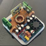
To be honest, i ended up avoiding really any calculations and bought a random core that was listed as a pulse transformer core 😳. Wound 4 primary strands 5 + 5 turns, and 20+20 secondary turns. Increased the frequency to 100khz to try and avoid the skin effect that was causing alot of heating, and added in soft start dead-time which removed the startup issue i was having that you predicted.
It puts out +/-55v and handles 350w rms and stays comfortably cool, so i am happy, as thats about how much power i need. Having 4 on each side was very overkill, at the moment 2 stay cold.
It puts out +/-55v and handles 350w rms and stays comfortably cool, so i am happy, as thats about how much power i need. Having 4 on each side was very overkill, at the moment 2 stay cold.
Attachments
Oh. Just spotted your other thread.
https://www.diyaudio.com/community/threads/12v-to-60v-0v-and-60v-circuits.412309/
You built a thing. When I burble at you remember that you built a thing. That makes you much better than me so don't think I am talking down at you.
Messages passed.
Skin/Layer effect works the other way around. Higher frequencies make it worse. Soft start, a gradually increasing pulse width, may/will save things. Dead time is, almost, always required and would have come with your control IC.
Again looking at your board, also your mention of a TL494, my other guess would be that you are operating without feedback so the IC is just producing a square wave drive to the Mosfets perhaps buffered with four transistors for some gate drive grunt.
You already appear or claim to be at 350W but there may be some doubt about how much you are actually getting because of the drop shop China amplifier you are using.
https://www.diyaudio.com/community/threads/12v-to-60v-0v-and-60v-circuits.412309/
You built a thing. When I burble at you remember that you built a thing. That makes you much better than me so don't think I am talking down at you.
Messages passed.
Wound 4 primary strands 5 + 5 turns, and 20+20 secondary turns. Increased the frequency to 100khz to try and avoid the skin effect that was causing alot of heating, and added in soft start dead-time which removed the startup issue i was having that you predicted.
Skin/Layer effect works the other way around. Higher frequencies make it worse. Soft start, a gradually increasing pulse width, may/will save things. Dead time is, almost, always required and would have come with your control IC.
Again looking at your board, also your mention of a TL494, my other guess would be that you are operating without feedback so the IC is just producing a square wave drive to the Mosfets perhaps buffered with four transistors for some gate drive grunt.
You already appear or claim to be at 350W but there may be some doubt about how much you are actually getting because of the drop shop China amplifier you are using.
No: this is the formula for squarewave. For a sinewave, you need to multiply the 4 of the denominator by 1.11 (the ratio of Pi/2 to sqrt2), see here for example: https://insights.globalspec.com/article/19378/fundamentals-of-transformer-designElvee gives an equation for Sine Wave excitation which will introduce an error.
Last edited:
Yes, though i first though this when i bought this cheap drop ship module, it is suprising how powerfull it is when you manage to buy one that uses legitimate components. I had to replace the mosfets on my module with legitimate ones in order to put out the 350w that i measured with my multimeter into a 4 ohm dummy load.You already appear or claim to be at 350W but there may be some doubt about how much you are actually getting because of the drop shop China amplifier you are using
Also, i appreciate the message

- Home
- Amplifiers
- Power Supplies
- DC-DC transformer core?