I have built this DC-DC convereter,and it´s working fine,but what if I want say 40volts/1.5 A,can I use a larger inductor for that?
And the switching frek is 16Khz I can hear it when I use it for an amp,can I use a LC or a RC filter?What values should that be?
And the switching frek is 16Khz I can hear it when I use it for an amp,can I use a LC or a RC filter?What values should that be?
Attachments
Nice site,my schema uses a bobin with no core,on the site it´s a
core,what´s the difference.
And I might be blind but I see nothing about the filter.
core,what´s the difference.
And I might be blind but I see nothing about the filter.
Why can't you just drop Ct to something like 350 picofarads, and then the switching frequency is up over 30kHz and you won't be able to hear it.. as per the appnotes page 4. I think its on the datasheet too
http://focus.ti.com/lit/an/slva143/slva143.pdf
As far as using a core, I think that just makes the inductor physically smaller.
http://focus.ti.com/lit/an/slva143/slva143.pdf
As far as using a core, I think that just makes the inductor physically smaller.
using a core will reduce inductor size...but be careful of saturation...as for higher voltages...just change the configuration of the feedback resistors...the formula can be found inside the datasheet I guess...it will also depend on the voltage reference.
So you are currently using this supply on an amplifier? how well does it perform? I ordered some samples and want to use this chip for a +/- 20 to 25 volt powersupply, at about 3 amps from the +12v in a car. I am wondering how well this sort of a setup would work, compared to a standard SMPS. I would like to avoid winding my own transformer and such, and this chip looks like the easy solution. Do you (ryssen) or any one else know how this would perform with a speaker as the load?
I know that voltage doublers and the like don't perform well with the variable impedance load that a speaker presents to the power supply, so I would like to be sure that this works before I get all crazy and make some pcbs.
Thanks
I know that voltage doublers and the like don't perform well with the variable impedance load that a speaker presents to the power supply, so I would like to be sure that this works before I get all crazy and make some pcbs.
Thanks
and it´s working fine
I am using a IRF830 instead of a BUZ 10,and and at low volume on the amp,it is 30 volts,but when i turn the volume up the voltage drops to say 12v,like the input volt.I will order a Buz 10 and try if it gets better. The amp is loaded with 3 ohms (2x40watts ic bridge amp)maybe the load is to low,and I wil try to
lower the osc cap for higher frekvency.will the current output get lower with higher frekvency?
I don't think that the capacitor will affect the current output. That appnote I posted has the formula for peak current as Ipeak=2*Iload*(Vout/Vin). In your case that would be Ipeak=2*3*(30/12)=15Amps. So you need to be sure you have a pretty fat transisitor in there. Looks like it is supposed to a high power bjt, maybe something like ON Semi 2N3772. Not sure exactly what will work there.
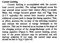
Also, your current limiting resistor appears to be the two .1 ohm resistors in parallel, giving .05 ohms. The formula for current limiting from that appnote is 0.5/(Ipeak) . (At least that is what it looks like to me, on page 14) that means you are limiting current at 10amps. Either add another .1ohm in parallel to give you 15 amps, or just get rid of them and connect the two pins together, giving no current limiting. (Altho you run the risk of letting out some smoke i suppose)
I think (hope?) that the reason your output is dropping to 12 volts is primarily because of the current limiting resistors. Before you replace your exsiting transistor, play with these values a bit, and if that doesn't work, then get a new transistor.
i may be wrong, but i think that the super low resistors are for current sense rather than current limit..and if they are for current sense, then you will need them
The resistors are used to limit the current to the load. I think they could be usefull, but at least for testing purposes can be omitted.
Also, the datasheet shows a bjt rather than a mosfet for the external transistor, not sure if that is a problem?
As far as the original question, (40volts @ 1.5 amps) the datasheet states maximum output voltage of 35 volts, recommended maximum of 30 volts. The inductor size is easy to calculate from the formulas on the datasheet or the appnote.
I have finally ordered the inductor and output transistor for this project and hopefully in a few weeks I can have a working prototype. I'll let you know if it all works out good.
From the appnote, the section on the current limiting resistor:
Attachments
A little uppdate,I have changed to a BUZ10 and it runns fine at 30 volts now,but the IC amp sounds better on 12 volts than 30 volts trough the converter.
Changed CT to 220pf it improved the soudquality,but i could still hear some switch frekqvensy in one chanel.When i touched the leads on the trasistor the switch sound dissapeared,and after a few minutes the convetrer stopped working,the out put was only 12v.Could the sound com from to long cables to the transitor,they are about4-5 cm.
Some very basic advice to do to reduce radiated & conducted EMI :
- Put CLC filters on the input and the output, use gapped ferrite inductors [they show higher impedance at RF than iron powder] designed to allow the required currents without saturation and low ESR capacitors. Filter response should be simulated, including capacitor ESR and inductor ESR in order to properly adjust L and C values to get enough attenuation above the switching frequency and little or no peaking [too big L with too small wire resistance and too small C may resonate and cause trouble]. With proper filtering ripple may be reduced to a few mV p-p and there won't be RF currents flowing through the input and output wires
- Put a common mode filter at the output or at the input. Use a high permeability ferrite core [preferably a toroid] and wind two identycal windings in the same direction [preferably one on each half of the core]. Use as much turns as you can but try to avoid input to output capacitance. This will also avoid RF currents flowing through the input and output wires
- Twist the input and the output wires, this prevents them to act as antennas
- Place the SMPS in a grounded metal case. This may add 20dB of attenuation to stray magnetic fields
- If there is ringing on the switching waveform, try a RC network in paralell with the switch or the diode. Orientative starting values are F_ringing=1/RC
- Put the switch, the input capacitor, the diode and the output capacitor toghether in a small PCB with as short tracks as posible, even for experimentation. The inductor should be also very close to that PCB. The longer the AC loops the higher the stray magnetic fields produced
- If you use the case as a heat sink, use thick insulators to reduce switch-case and diode-case capacitances
This picture shows the layout of a simple boost converter I designed some time ago. Input was 10 to 16V and output was 20V at 6A. It features basic functionality like soft start, current limiting, limited maximum duty cycle and under-voltage lockout. Control circuit and the gate of the MOSFET are powered from the regulated output for convenience since a Vg-s of 19V reduces conduction losses. IC1 is a TL494 and I think the rest of the circuit is rather self explaining
An externally hosted image should be here but it was not working when we last tested it.
Hey Guys,
Could you tell me what MOSFET other than the BUZ10 can be used for the smps because its a bit hard to find?
Thanks
Could you tell me what MOSFET other than the BUZ10 can be used for the smps because its a bit hard to find?
Thanks

- Status
- Not open for further replies.
- Home
- Amplifiers
- Solid State
- DC-DC converter