having fun scanning
As long as I had the scanner out, I thougth I would post some earlier ideas as images. Here is the bucking coil idea applied to two SE amplifiers in post 76. The windings get series connected in phase to cancel out the AC so a DC voltage supply can be used, internal winding resistance limits current.
By the way, I tried to draw up the two P-P center tapped transformer version (2nd paragraph, post 76) and realized it is not working, unless one comes up with a P channel tube for one of the ampls, could use a P chan Mosfet on one amplifier I guess. My appologies to Piergiorgio on the confusion I caused. Using all tubes, one does indeed end up with the CrowHurst Twin Coupled amplifier to get polarities right.
Don
Attachments
correction
OOps, the bucking coil compensator schematic in the last post should show the grid signal to one amplifier inverted in polarity with respect to the other amplifier.
OOps, the bucking coil compensator schematic in the last post should show the grid signal to one amplifier inverted in polarity with respect to the other amplifier.
Norman's design is using the leakage reactance of the xfmr to provide separation of the treble between the two channels. Only working for the treble since the leakage reactance is small compared to the individual primary reactances.
It would seem that way at first glance, wouldn't it? At low frequencies there is little signal delivered to the L and R channels anyway, and according to Crowhurst: "Immediately above crossover, up to a frequency where the leakage inductance between left and right windings is directly adequate to provide separation, the third winding also serves to improve separation. The sum signal across it is split in two and subtracted from the partially-coupled signals appearing across the main windings. The result is that each output is much more fully separated from the other."
Note that the third winding has exactly twice the number of turns as either main (treble) winding.
Hi Dave C.
Ahhh! The first time, I didn't pick up on the common winding being used as the other terminal for the Left and Right windings. So he subtracts out the common signal to get more separation. I guess the 100 pF is there to drop out the HF from the common winding once the L and R start working with enough leakage reactance for separation. Clever design. I wonder how smooth the frequency response is.
I believe there was a thread on another design with two channels on one transformer within the last 6 months here. It was some historical published design, used two output tubes. I can't recall what it was called or how it worked. My first guess would be something with differential mode and common mode, but I can't seem to come up with a workable scheme off hand. Maybe someone remembers the thread? Using a figure eight core, or E - I core, one can, of course, just use the two magnetic loops for separate transformers like I did above in "something for nothing".
Westinghouse used a scheme with one big output xfmr for the common signal and a small output xfmr for the difference signal. Multiple secondaries combined these back together to get L and R channels. Hmmm, how about using P-P to get the common signal and SE to get the difference signal. Could use a gapped E core with a gap only on the center leg. Then the outer ring works as P-P and the center leg works as SE with a gap. The two secondaries then get placed in the correct positions to pick up the common P-P signal with + or - the SE signal summed in the flux thru that link. Bet that was how the idea worked using the single xfmr.
Don
Two In One Amplifier
Hows this?
This has GOT to be the way they did it. P-P operation for the common signal (+L+R) and SE operation for the difference signal (L-R), all using the same output tubes. The secondaries get arranged as shown to re-multipliex the sums for L and R outputs.
Someone will probably recognize the scheme now and tell us who invented it.
All these two in one schemes "suffer" from having to use class A operation however. You could do class AB if one put the two signals on the separate loops of the E-I figure eight, but would require 4 output tubes. These were probably all some contest to see who could chop the most parts out though.
Attachments
they are the same!
As soon as I got offline I realized the last schematic I drew up is virtually the same as N. Crowhurst's. Just drawn with a more optimal tranformer core design so the functionality is obvious. Probably N. Crowhurst used the same gapped E-I core design too, but drew the schematic figure as a square core for easier layout of the windings. Then just added the 100 pf cap to patch up the frequency response. Amazing how the layout of a schematic can change its perceived operation so much. Explains why I get lost hiking in the woods when it starts getting dark out, nothing looks the same.
As soon as I got offline I realized the last schematic I drew up is virtually the same as N. Crowhurst's. Just drawn with a more optimal tranformer core design so the functionality is obvious. Probably N. Crowhurst used the same gapped E-I core design too, but drew the schematic figure as a square core for easier layout of the windings. Then just added the 100 pf cap to patch up the frequency response. Amazing how the layout of a schematic can change its perceived operation so much. Explains why I get lost hiking in the woods when it starts getting dark out, nothing looks the same.
PC Dc compensation maybe this works
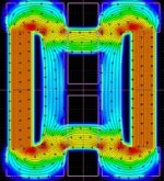
See below a schetch of a proposed arrangement made by standard lamination and magnet. red and blue are the polar expanion of a strigh 1Tesla magnet. Gray is the soft magnetic core, dark green two coil of 2500 turn 250mA.
The filed in this arrangement is below the saturation in each part of the AC path. See next post for the filed distribution.
Attachments

Hi Piergiorgio,
It appears that the magnets can improve the field level in the coil sections or the non-coil sections depending on polarity, but not both at the same time. Maybe can put more lamination thickness in the most needed sections, but that may pull more magnet field thru it then too. Also, I suspect that the mechanical fit of the magnet to the lamination will be critical to getting the field strength correct.
The assembly of the laminations with coils will place the mechanical freedom axis to tighten the fit in the wrong direction to put pressure on the permanent magnets. But maybe could put a slight taper in the lamination to magnet contacts so the magnets can be pressed in to some pressure level, or even some measurement of flux made while pressing them in.
The magnets will still be opposed to the electromagnet in this configuration, so their demagnetization over time will still be a concern too. I suppose one could use electromagnets for the bucking field, so demagnetization would not be a concern, but might as well put them over the primaries directly then.
I still am convinced that a circuit design approach is the most practical way to solve the DC compensation problem.
Don
DC compensated Single Ended OPT
Hi all,
I have gone with interest through the discussion on DC compensated single ended OPT ( gapless). Congratulations Mr. Scarpa, it's a very interesting subject.
However I missed some of the variants, especially those concerning the use of a permanent magnet (but this looks to me quite critical).
In an old booklet I found in my modest library ( Radio Shack -
Math for the Electronics Student - # 62-2057 ) that I had bought for 1$95cts ( imagine how old it is ), there is a chapter that applies to our debate : "Inductor combinations" - Page 73 .
In the case of series opposing windings , you have:-
Lt = L1 + L2 - 2M
where M is the mutual inductance, determined by the formula
M = K * sq.root( L1*L2 )
K being the coefficient of coupling.
If we want to have a simple ( though somewhat expensive, efficiency wise ) solution, we should loosen the coupling as much as possible .
In fact, if we could lower the coupling coefficient to 0.8 , we would loose roughly 30 % of the primary impedance, even with a large capacitor shunting the opposing coil ( as suggested by Farber).
This loss can be recovered by increasing the number of turns both on primary and opposing coil ( and secondary, of course, to maintain the required ratio ).
The lack of an air gap should keep this kind of transformer to a reasonable bulkiness, even if the idle dc current is very high.
And this is where the solution is interesting. Stronger valves can be used and more power delivered in single ended configuration.
Hoping I did not made any blunder, what are your comments ?
Gigi
Hi G. Cesar or, better, Ave Cesare!
I see no point to intentionally decrease the coupling and enhance th turns to account for minor coupling.
What you need is a strong coupling in dc to effectively compensate for the dc flux and a weak or none coupling in ac, so Your primari does not see the aux winding as shorted secondary.
Maybe this can be done with some particular geometry, and I'm trying to get a suitable arrangement for permanent magnet solution (that is better because requires less winding and no efficiency problem). Till now there are just some teoretical schetches that can works but I wasn't able to find a perfect geometry.
Hi Gigi,
I see Piergiorgio has beat me to it. I agree with him. Loosening the coupling will also weaken the DC flux cancellation too.
Don
A configuration I don't think has been mentioned yet is the dual core one used in magnetic amplifiers. Take two toroid cores say, side by side. On winding goes over both toroids, the other goes as a figure eight around both. This way they do not couple to each other AC wise. Unfortunately, one core can have its flux cancelled but the other gets its flux doubled. This means only half the saturation (or less) level can be used. I think the net result is that it comes out to the same amount of iron as just using an external inductor like in parafeed or figure 3 of Farber.
Hi Piergiorgio , Hi Don,
I made the following experiment :
I took one half of a C core and fixed it upside down with its two
bobbins ( primary and DC balancing, that I will call the tertiary for simplicity ), well secured to a vertical support.
Underneath I slipped the second half of the core and, of course, with DC flowing in one of the cores only ( whichever) and a sufficient amount of current, this second half remains attracted, in spite of its weight.
Now, putting the two windings in opposing relationship and letting the same ( or much more ) current flowing, the second half of the C core drops ( falls). To make sure that I could easily control the experiment, I fitted two parallel variable resistances,
to each coil, so that I could let more current flow in one winding and less in the other or vice-versa.
Does this mean that, even with a loose coupling, you can assure the zero level flux required ?
I think yes. After all we can play with Ampere's law of ampere turns.
Can someone try and let me have a confirmation or objections?
Gigi
G.Cesar said:(...) ( primary and DC balancing, that I will call the tertiary for simplicity )
Hi Ari, we missed You in this discussion.
The experiment You made tell us only of DC flux flowing more or less in the magnetic path. The key point is that in the Farber condenser arrangement and in yours tertiary coils DC compensated transformer the aux or tertiary winding shoerted by the cap greatly reduces the power transfer efficiency of the audio signal from primary to secondary.
Much better the inductance Farber arrangement that can be modified as I propose to achieve also a cathode resistor for free.
In my opinion better will be the Permanent magnet DC flux compensation, if there will be some practical solution. Just for conceptual experimentation, not for cost because I guess that an extra inductance cost less than the required magnets.
Ciao Piergiorgio.
It is certainly interesting to find out which one is the best.
Have you tried the arrangment you suggested?
I am collecting some results on samples and will send them asap.
Tomorrow a friend of mine will come with some instruments and we will try to measure the coupling coefficient and all other useful parameters.
Talk to you (all) soon.
Ciao Ari,
I used the Farber's Fig. 2 arrangement in few small TV tube stereo amplifier to use some small cheap PP output trannies found on a flea market. Despite to the appearance this 50 euro stereo amplifier works in the sense that is possible to listen at it and the overall tone is acceptable.
The DC compensating arrangement gives more bass impact to these amplifiers comparing to the same size PP tranny readjusted to put a small gap in.
Also some small toroidal transformer 115+115 /10+10V works.
As pointed out in this discussion, the big price to pay is efficiency. I don'y made any measurement on these my very first amplifier and in particular on the power output and distortion. I may estimate that a PCL86 with Geloso out tranny can give 0,5W without appreciable distortion. Some friends of mine may still have this amplifier (we're speking of maybe 10 years ago)
The discussion made in this 3D and with some other people lead to propose an alternative arrangement, slighty modifying the Farber's original proposal. I Think that the inductor on cathode and the aux (or tertiary) winding can have some advantages over more conventional topology, especially with high current tubes.
I'm simulating a 6080PSE to find out a suitable output transformer data. Yves is working also on this circuit and has higher capacity than me to design and maybe produce the output trannies. I have no great experience and no winding facilities at all. If somebady can send me some trnsformer I will try it for sure ;-).
Ciao
Hello Piergiorgio, Hello Yves,
I will be happy to learn about your results.
The best performances are, as you can imagine, with low plate resistance tubes, that need low inductances. I tried with the 6C33C-B at 220-230 mA ( 16W output - SE ) and even three of them with a total idle current of 700 mA (output power 50 W). Needless to say, the bass is there.
Looking forward to your simulated calculations on the 6080 whose plate resistance is quite low.
All DC compensated Farber mods
Hi all,
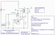
reasoning a little bit on the proposed arrangement previously posted, I'm wondering why not this circuit, replacing the inductor with cheap mains 115+115V transformer compensating the DC as in Farber works with a simple capacitor?
In this case efficiency is not an issue, because inductor is not interested by ac signal (is shorted before by C1.
My simulator refuse to work with this circuit, give violation address! But with old paper and pen means seems reasonable.
Hi all,
reasoning a little bit on the proposed arrangement previously posted, I'm wondering why not this circuit, replacing the inductor with cheap mains 115+115V transformer compensating the DC as in Farber works with a simple capacitor?
In this case efficiency is not an issue, because inductor is not interested by ac signal (is shorted before by C1.
My simulator refuse to work with this circuit, give violation address! But with old paper and pen means seems reasonable.
Attachments
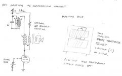
Yet another variant
The upper reported circuit has the disadvantage that is not easy to tweak for best combined AC and DC performances, due to the presence in the cathode circuit of two resonating tanks and the interacting positive feedback at the low end.
So this other variant reported here can be easily tweaked to have best Ac transfer (Bode diagram's) flatness and extension.
Also there is no need of separate connection for cathode, so all the two transformer (fox example cheap toroidal lightning transformer) can be potted in the same can with the decoupling Cap. So we have a high-end appearance at maybe performance at a fraction of prices. For sure at a fraction of weight!
Attachments
- Status
- Not open for further replies.
- Home
- Amplifiers
- Tubes / Valves
- DC compensated SE output transformer