Hello,
This is my first thread here so please forgive any mistakes. English is not my native language.
I started building a DC blocker for my AV set-up devices: Pioneer VS-LX305 multi-channel amplifier in a 7.1.2 speaker configuration, Panasonic HD DP-UB424 BD Player + a few smaller components.
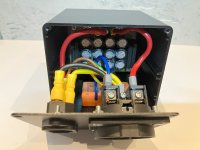
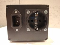
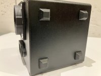
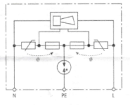
When building a DC blocker, I wanted to use a ready-made solution. No, not high-end because I don't expect a miraculous improvement in sound😉 I just want to proactively protect the equipment from a possible DC component so I bought a medium-sized module on Aliexpress. The schematic was not included, I drew it in LTspice:

Question #1:
What do you think about such a DC blocker? It seems a bit oversized or maybe even exaggerated, but it is built rather classically.
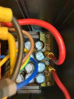
The total capacity is 9900uF and consists of 12 pieces 3300uF/10V capacitors connected in opposition (as bipolar). I want to believe that the Nichicon print on the capacitors means real Nichicon and not "clones"😉
I have doubts about the huge number of diode bridges. There are 6 bridges (KBJ2510 1000V / 25A), which means there are 24 diodes in the system. Please correct me if I'm wrong: diodes connected in this way will limit the maximum reverse voltage on the capacitor pairs to a maximum of 2.5-3V. In my opinion, this means that the reverse voltage on a single capacitor will be 1.25-1.5V. It seems to me that this is a bit too much. I would prefer to stick to the maximum reverse voltage of 1V on a single capacitor.
On the other hand, diodes connected in this way ensure blocking of the DC component to 3V. In my home installation, I absolutely do not expect such a high DC component, so the value of 3V in my case is oversized.
Question #2:
Would removing two bridges with diodes D17.. D24 be a reasonable move? What do you think? This would reduce the reverse voltage on the capacitor pairs to a maximum of 2V. Of course, the DC component in the home network would then be blocked to 2V and not 3V.
I would be happy to hear all opinions on the subject I have raised 🙂

This is my first thread here so please forgive any mistakes. English is not my native language.
I started building a DC blocker for my AV set-up devices: Pioneer VS-LX305 multi-channel amplifier in a 7.1.2 speaker configuration, Panasonic HD DP-UB424 BD Player + a few smaller components.
When building a DC blocker, I wanted to use a ready-made solution. No, not high-end because I don't expect a miraculous improvement in sound😉 I just want to proactively protect the equipment from a possible DC component so I bought a medium-sized module on Aliexpress. The schematic was not included, I drew it in LTspice:
Question #1:
What do you think about such a DC blocker? It seems a bit oversized or maybe even exaggerated, but it is built rather classically.
The total capacity is 9900uF and consists of 12 pieces 3300uF/10V capacitors connected in opposition (as bipolar). I want to believe that the Nichicon print on the capacitors means real Nichicon and not "clones"😉
I have doubts about the huge number of diode bridges. There are 6 bridges (KBJ2510 1000V / 25A), which means there are 24 diodes in the system. Please correct me if I'm wrong: diodes connected in this way will limit the maximum reverse voltage on the capacitor pairs to a maximum of 2.5-3V. In my opinion, this means that the reverse voltage on a single capacitor will be 1.25-1.5V. It seems to me that this is a bit too much. I would prefer to stick to the maximum reverse voltage of 1V on a single capacitor.
On the other hand, diodes connected in this way ensure blocking of the DC component to 3V. In my home installation, I absolutely do not expect such a high DC component, so the value of 3V in my case is oversized.
Question #2:
Would removing two bridges with diodes D17.. D24 be a reasonable move? What do you think? This would reduce the reverse voltage on the capacitor pairs to a maximum of 2V. Of course, the DC component in the home network would then be blocked to 2V and not 3V.
I would be happy to hear all opinions on the subject I have raised 🙂
Last edited:
Why not first try it out?
If your devices have classic EI transformers or SMPS you will probably not even notice any DC component in the main voltage. It are mostly toroids that are allergic to that and hum as a result.
Then a mains filter would have made more sense. To filter out RF that is around us everywhere.
If your devices have classic EI transformers or SMPS you will probably not even notice any DC component in the main voltage. It are mostly toroids that are allergic to that and hum as a result.
Then a mains filter would have made more sense. To filter out RF that is around us everywhere.
Last edited:
Firstly I doubt any equipment would be damaged by an offset. We call it 'DC' but its more an asymmetry of the AC waveform that gives a shift away from an average of zero (for a pure sine) rather than a pure sine sat on some DC voltage. Its a subtle difference but one to be aware of.
I wouldn't worry over much and would keep the design as it is I think. You could measure and see what sort of voltage you see across circuit end to end (beware as it is live of course)
If it makes you feel happier you can short out a pair of bridges as you suggest but I really don't see a need. If you actually did start to see highish levels of 'DC' then you really have got problems with your mains supply which I doubt.
One thing the diodes will do is prevent excess surge current in the caps if for example you are running a big amp with a big transformer. By limiting the voltage across the cap the current in the cap is limited during that high inrush period. When drawing a normal sort of load current (for an audio set up) the diodes play no part. Use it with a 3kW heater and its probably a different story.
Also if you remove a pair of bridges then the LED's will never see enough voltage to ever light.
I believe that these interferences are really dangerous to the equipment. I have pretty good RFI/EFI CW4L2-20A-S filter + surge protector in my line conditioner TAGA Harmony. I've eliminated this issue months ago🙂Then a mains filter would have made more sense. To filter out RF that is around us everywhere.
Thanks for reply.One thing the diodes will do is prevent excess surge current in the caps if for example you are running a big amp with a big transformer. By limiting the voltage across the cap the current in the cap is limited during that high inrush period. When drawing a normal sort of load current (for an audio set up) the diodes play no part. Use it with a 3kW heater and its probably a different story.
Also if you remove a pair of bridges then the LED's will never see enough voltage to ever light.
My amplifier has a declared power consumption of 750VA if I remember correctly, so I have a much much lower power requirement than 3kW.
Yes, I know, the LEDs will not light up if the voltage on the bridges connected in parallel to the capacitors is lower than 2V. But that is not my main concern. In many threads I have seen information that the electrolytic capacitor VERY much does not like reverse voltage higher than 1V. I am afraid that this system with 24 diodes will not provide them with such protection.
Last edited:
In many threads I have seen information that the electrolytic capacitor VERY much does not like reverse voltage higher than 1V. I am afraid that this system with 24 diodes will not provide them with such protection.
I think in practice it is not an issue...
The low voltage caps will have a low leakage current when correctly biased and a higher leakage current with small reverse bias. One cap in the pair is always correctly biased. If we substitute resistors for the leakage we get a high value in series with a low value. The correctly biased cap limits current flow (that cap doesn't care the other is reverse biased) and the reverse based cap (the lower resistor value) see only a small voltage.
Just for fun and it doesn't model leakage. The bit at the left I took from Rod Elliots example of asymmetry on the mains and how it occurs.
I'm not quite sure why the offset is not zero, maybe because it is not a DC offset as such as applied but a more of a harmonic distortion.
Attachments
I made a simulation in LTspice for a 50 Ohm load, which is of course an irrational example. The output waveform in LTspice remains unchanged, so in my opinion the simulation is not able to correctly display the waveform for such extreme conditions. In the case of such a large load, the diodes will conduct current and the sinusoidal waveform in the area of zero crossing will be very non-linear and the harmonic content will be clearly noticeable, right? I don't see anything like that in the LTspice simulator.I'm not quite sure why the offset is not zero, maybe because it is not a DC offset as such as applied but a more of a harmonic distortion
LT shows the average DC level is lower after the blocker but harmonic content looks unchanged. The caps reactance is so low that you should not ever see the diodes come into conduction in normal use. If you make the caps a lower value you will see significant current in the diodes.
Raw mains, pure.

And Vin before the blocker:

And Vout:

Raw mains, pure.
And Vin before the blocker:
And Vout:
I tested this DC blocker today and connected it between the power supply and the toroid that powers the halogens. This toroid always buzzes a bit. The effect surprised me. The buzzing did not decrease and even increased slightly. I repeated the test 3 times and each time the comparison effect was the same. This DC blocker is not for someone who wants to silence a buzzing toroid.
Your findings are interesting. I've never built or even tried a DC blocker at home... dunno... interesting results though.
It would be nice to know details like brand, type, VA rating, actual load and of course measured mains voltage and for what mains voltage the primary winding was wound.
Also to avoid that people think DC blockers never work based on 1 (one) case.
BTW I recently bought a few surplus A brand toroids wound specifically for halogen lighting. I do not know what makes these specifically for halogen lighting (except the 11.5V and lower secondary voltages) !?! They do have overtemp protection which is not standard for normal toroids.
Last edited:
Are you sure your toroid's buzzing is caused specifically from DC applied to the transformer via the power line? If not, designs like this are not for you. Some of us have had great success with conceptually similar designs.I tested this DC blocker today and connected it between the power supply and the toroid that powers the halogens. This toroid always buzzes a bit. The effect surprised me. The buzzing did not decrease and even increased slightly. I repeated the test 3 times and each time the comparison effect was the same. This DC blocker is not for someone who wants to silence a buzzing toroid.
- Home
- Amplifiers
- Power Supplies
- DC blocker - ready to use but there are a few doubts
