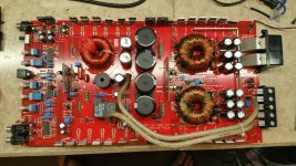
I bought a blown DB drive A7-2000.1 to tinker with. The power supply in the amp is good, it powers up normally, not in protect, but it does not produce audio. It looks like someone has monkeyed with it before me. There was a shorted 12V zener that supplies the driver module, it had been cut out and soldered back in. I replaced it. There is also a SMD diode missing from the driver board. The other one in the same package on the board is 639A, I searched high and low for that, and it looks like it might be a 18V zener transient surge suppressor. I would like confirmation if anyone has the info.
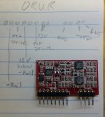
Also, the typical defaced IC's. In the photo of the driver board, you can see that I started identifying it's pinout. The lower right IC has typical op-amp arrangement, I haven't figured out the upper right one yet (it's not +/-15v though) , but the left hand one appears to get it's power from the aforementioned 12v zener, and it has a pin that goes to each set of FET gates.
Any help deciphering would be appreciated!
*edit* pics coming in a second, I need to resize them...
**edit 2** on the picture of the driver board, where it says 12v below - rail, it should actually read 12v above - rail. Meaning the lm7812 is referenced to the negative rail instead of ground.
Thanks,
Jason
Last edited:
My copy of the tutorial has muting transistors as item 13 on the class D type 3 page. There also does not appear to be a close match to this board in my copy. The DWM3460 schematic has a lot of similarities, but the diodes aren't labeled in the schematic. I also do not see any of these with two TL072's.
The first picture of the 3S driver, the one that looks like it is meant to drive a dual mono or BTL configuration has what appears to be X355 in what I think may be the same position as my driver. It uses four of the same.
Perry, has the tutorial been updated with a bunch of new information here? If so, drop me an email about purchasing a copy of the new version.
Thanks,
Jason
Is anything after the muting transistors? That's where the diode info is.
The type 7 page shows a driver board with two TL072s.
The mark is X3.
Is the bbb at sbc still a good email?
There have been updates.
There is no way to buy an update other than buying the tutorial as you did the first time. I have a lot of notes to add but haven't had time. I hope to do it in the next couple of months.
Perry, no, there is nothing in mine after the muting transistors section. I've attached a screenshot with the information blocked out to protect your content. I also do not have a class D type 7 section. My tutorial is probably 6-7 years old, maybe older. I do not mind buying it again, but if you are about to update it, I would just as soon wait until your new notes are in.
The SBC email is still good, I also have the same address at gmail, and I actually prefer that one, but I check both regularly, so I'm not too choosy.
Thanks,
Jason
The SBC email is still good, I also have the same address at gmail, and I actually prefer that one, but I check both regularly, so I'm not too choosy.
Thanks,
Jason
Attachments
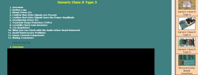
where is the web site in the photo<?Perry, no, there is nothing in mine after the muting transistors section. I've attached a screenshot with the information blocked out to protect your content. I also do not have a class D type 7 section. My tutorial is probably 6-7 years old, maybe older. I do not mind buying it again, but if you are about to update it, I would just as soon wait until your new notes are in.
The SBC email is still good, I also have the same address at gmail, and I actually prefer that one, but I check both regularly, so I'm not too choosy.
Thanks,
Jason
It's not a site. It's a tutorial I sell.
...And it is worth it's weight in gold. Even for the folks with more experience, it's not outlandishly expensive, and if nothing else it helps pay a little back to Perry for all of his years of helping pretty much all of us out of one tough problem or another!
Perry, I got the email. Thank you.
Jason
ok, where i can buy this?It's not a site. It's a tutorial I sell.
if you want, can you tell me how much cost in pm?
$50US
There is a banner for it on the bottom of virtually every page of my car audio site (link in sig file below).
A couple of notes...
It's designed for those relatively new to repairs but has some advanced information.
It's not a video. Anyone buying it will have to do MANY hours of reading.
There is a banner for it on the bottom of virtually every page of my car audio site (link in sig file below).
A couple of notes...
It's designed for those relatively new to repairs but has some advanced information.
It's not a video. Anyone buying it will have to do MANY hours of reading.
Hi folks, I am back working on this project again. I replaced the half bridge driver with a new one ordered from Mouser. I replaced the missing diode with STPS4S200UF, a schottky diode rated at 200V and 4A. I also replaced both TL072's. I checked the amp briefly out of the sink. It powered up and produced audio. I fully reassembled and put it on my 100A power supply and hooked it up to the shop sub to do some moderate volume testing. It played for about 5 minutes, then the sub popped and the amp went into protect. The sub is fine, but the amp now has about 22V dc on the output for a brief moment before the protection shuts down the power supply. It very well could be going to full rail voltage before shutdown, but it happens to quickly to capture on the DMM.
Anyhow, I had installed a socket for the driver in case I had more trouble, with the driver board removed the amp powers up fine. In circuit the outputs are checking fine. If I install the driver and check them they all show leakage from gate to drain. I'm guessing something went on the driver board and am looking for advice on what to check first.
Thanks,
Jason
I checked all the resistors, diodes, and the 2 sot23 transistors on the driver board and they all check out good. There is a small diode between the two tl072's that tests shorted while on the board, but I pulled it and it tested fine. I removed the 2184s and the amp powers up with no issue so I swapped the 2184s again thinking it must have shorted. New driver in place and it still goes into protect.
Thanks in advance!
Jason
Thanks in advance!
Jason
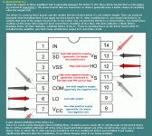
Using the guide (below) for the 21844, check the resistance for each combination of pins on the 'good' IC you removed and one that's never been installed.
If you get significantly different reasons, the IC may have been damaged when installed.
If you get significantly different reasons, the IC may have been damaged when installed.
Attachments
Thanks Perry, I tested all the 2184s including the factory defaced one. They all check out good. Further testing shows that the low side fets are seeing about 1V on their gate referenced to source before the amp goes into protect.
I'm going to pull the low side fets and see if any are leaky. Is it normal to have IRF640N in the output stage of these amps? I have fought issues with "N" suffix parts in the past. I try to not use them unless I can confirm that was the factory part.
Thanks,
Jason
I'm going to pull the low side fets and see if any are leaky. Is it normal to have IRF640N in the output stage of these amps? I have fought issues with "N" suffix parts in the past. I try to not use them unless I can confirm that was the factory part.
Thanks,
Jason
I think I have the problem solved. I unclamped the low side fets and the amp powered up normally. I believe I nicked the kapton tape I used for insulation. I cut out that piece and installed sil pads and the amp is working again. I am going to do some more audio testing. Thank you so much for your help!
Jason
Jason
Nope, not fixed after all. I put a load on it and it went straight into protect again. Tested the half bridge driver and it was blown. I unclamped the fets again and even with a new driver again it still goes into protect. New driver tests fine. I will have to unclamp the high side fets tomorrow and make sure they are ok. I'm probably going to pull all the fets and test individually. I have a stinking suspicion that this ,ay all be symptoms of the 640N parts. Can anyone confirm if they were the original parts?
*edit* I just noticed your reply above Perry. I will try to look at it tomorrow. I had to head back to the house to get the little ones lunch. I'm having some problems with my back and am only able to spend a few hours at a time in the shop. I will have to continue troubleshooting tomorrow. Thank you for your assistance.
Thanks,
Jason
Last edited:
- Status
- This old topic is closed. If you want to reopen this topic, contact a moderator using the "Report Post" button.
- Home
- General Interest
- Car Audio
- DB drive OKUR A7 2000.1 driver