im restoring one of these amps. it had bad outputs. i replaced them and the drivers and now it plays but my positive rail voltage is at 95v and my negative is -74v. i cant find why the positive rail is going so high. having a brain fart. any suggestions?
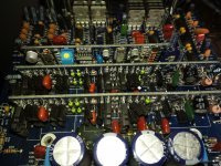
There were at least 2 versions. Post a photo of the main and driver boards.
The problem with uneven rail voltage is generally due to bad drivers but I'd expect more than a 20v difference if the amp was driven into a load.
The problem with uneven rail voltage is generally due to bad drivers but I'd expect more than a 20v difference if the amp was driven into a load.
I'm not familiar with that amp, but from years of industrial induction motors and transformers, I would check your power transformer for the beginnings of a rub through short. It may have just shorted a winding or two on one side. Thus causing that side to have a few turns less, and a lower voltage but not enough yet to cause it to over current. With no power applied, and all the caps discharged. give the power supply inductor a wiggle and also try to wiggle the individual turns, see if you find a loose spot and inspect it well.
It's possible to have a primary to secondary short that will lift the secondary by about 12v (could be possible here). A shorted primary to primary or secondary to secondary will cause VERY high current draw. Since both positive and negative rails both get charged from both secondary windings, a shorted winding can't cause an imbalance from one rail not getting as much voltage.

I don't know if this applies to all types (topologies) of class D but the rail with the bad drivers is generally the one that goes too high (too far from ground). That would seem to indicate that the high-side isn't driven properly. Both driver boards likely have defects.
Did you look at the drive signals for the outputs with a scope?
Did you confirm that the low value resistor linking the emitters of the drivers were within tolerance?
Did you confirm that you have 12v across all of the 12v zeners on the driver boards?
If you're not familiar with the basic design of the circuit, the following amp is similar, as far as the circuit is concerned. 'PDF' page 24 is the output circuit diagram.
- Status
- Not open for further replies.
- Home
- General Interest
- Car Audio
- db drive 2000.1