Hi,
I've been through three of the Dayton Audio SPA250 plate amplifiers over the last three years. This is my third one, and PartsExpress is no longer interested in honoring their warranty.
The failure is always the same; It starts popping. One pop here. One pop there. It can be 10 minutes between pops, or four days, and at any time of the day or night with no regard to source being active or not. Eventually, it just barely works.
I'm driving a single Dayton Audio RSS265HF-4 10" Reference HF Subwoofer 4 Ohm, sealed in a sealed enclosure, using the dedicated sub-woofer output of my Onkyo amplifier to feed the plate.
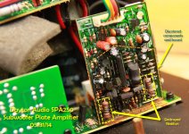
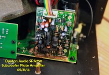
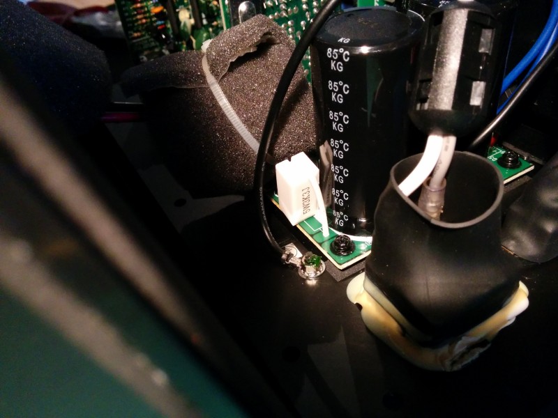
Q: If anyone has this amplifier, would you be willing to help me identify the two resistors shown in this picture? Specifically, could you open your amp and take some photos/color bands from it?
You'll notice everything is nicely charred. However, I could not find any other evidence of blown components.
Thanks greatly, in advance.
I've been through three of the Dayton Audio SPA250 plate amplifiers over the last three years. This is my third one, and PartsExpress is no longer interested in honoring their warranty.
The failure is always the same; It starts popping. One pop here. One pop there. It can be 10 minutes between pops, or four days, and at any time of the day or night with no regard to source being active or not. Eventually, it just barely works.
I'm driving a single Dayton Audio RSS265HF-4 10" Reference HF Subwoofer 4 Ohm, sealed in a sealed enclosure, using the dedicated sub-woofer output of my Onkyo amplifier to feed the plate.
Q: If anyone has this amplifier, would you be willing to help me identify the two resistors shown in this picture? Specifically, could you open your amp and take some photos/color bands from it?
You'll notice everything is nicely charred. However, I could not find any other evidence of blown components.
Thanks greatly, in advance.
Attachments
Sorry I cant help there but your thread might get more attention here Solid State - diyAudio
PE must get a lot of complaints on those, I read so much bad talk on several sites about Daytons plates that I cancelled an order on one of their 500s. It sounds like good power is there and the built in amp eq combo is great but dependability lacks.
PE must get a lot of complaints on those, I read so much bad talk on several sites about Daytons plates that I cancelled an order on one of their 500s. It sounds like good power is there and the built in amp eq combo is great but dependability lacks.
Last edited:
Thanks for your reply. I want to experiment, but I need to know what it was, before I decide where I want to go with it. Beats dropping another $100-130 on yet another one.
PE Plate Amp
Hi Nixit-
Had the same problem with a PE amp. The board in question contains the soft limit circuit for the amp. The 2 resistors should be marked RS1 and RS2. They are dropping resistors to reduce the +-Vcc for the boards op amp to 15v. They work with 2 zeners that should be marked ZD3 and ZD4. The resistors are probably under rated at 1/2watt. If you replace them go with something larger and also check to make sure the zeners are good. See attached schematic.
Good Luck
Steve
Thanks for your reply. I want to experiment, but I need to know what it was, before I decide where I want to go with it. Beats dropping another $100-130 on yet another one.
Hi Nixit-
Had the same problem with a PE amp. The board in question contains the soft limit circuit for the amp. The 2 resistors should be marked RS1 and RS2. They are dropping resistors to reduce the +-Vcc for the boards op amp to 15v. They work with 2 zeners that should be marked ZD3 and ZD4. The resistors are probably under rated at 1/2watt. If you replace them go with something larger and also check to make sure the zeners are good. See attached schematic.
Good Luck
Steve
Attachments
Forgot to mention that you can eliminate the circuit altogether by putting in a fixed resistor in place of the one inside photoresistor U2. This resistor is in the feedback divider network and hence controls the amps gain. I think I wired mine for a gain of around 25. Not too critical since there is a gain control built into the amp.
Damn, i was looking at buying one these amps. Still, this wouldn't put me off buying one. I'd rather buy an amp with a known failure mode than another chinese amp with unknown failure modes.
What are the main rails in this thing? I guess about 50-55V unloaded to deliver 250W into 4ohm? This gives around 0.66W dissipation on those resistors (assuming the schematic is correct that they are 2.4Kohm). I guess it's not unreasonable to them to burn out eventually - they look like 1 or 2Watt carbon resistors.
I guess if they are replaced with 10Watt resistors everything should be apples.
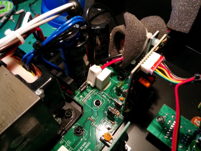
[following pic] has this little guy got toasty too, or is it just soot from the nearby resistor? Which resistor is it in the schematic?
Cheers,
-Tim
What are the main rails in this thing? I guess about 50-55V unloaded to deliver 250W into 4ohm? This gives around 0.66W dissipation on those resistors (assuming the schematic is correct that they are 2.4Kohm). I guess it's not unreasonable to them to burn out eventually - they look like 1 or 2Watt carbon resistors.
I guess if they are replaced with 10Watt resistors everything should be apples.
[following pic] has this little guy got toasty too, or is it just soot from the nearby resistor? Which resistor is it in the schematic?
Cheers,
-Tim
Attachments

There were other burned components on my Amp also as well as some fried board traces. That's why I elected to circumvent the whole soft limit board as described in the previous post.Damn, i was looking at buying one these amps. Still, this wouldn't put me off buying one. I'd rather buy an amp with a known failure mode than another chinese amp with unknown failure modes.
What are the main rails in this thing? I guess about 50-55V unloaded to deliver 250W into 4ohm? This gives around 0.66W dissipation on those resistors (assuming the schematic is correct that they are 2.4Kohm). I guess it's not unreasonable to them to burn out eventually - they look like 1 or 2Watt carbon resistors.
I guess if they are replaced with 10Watt resistors everything should be apples.
[following pic] has this little guy got toasty too, or is it just soot from the nearby resistor? Which resistor is it in the schematic?
Cheers,
-Tim
Bonfis, Thanks so much for your reply.
Can you tell me how you bypassed the soft limit circuit at the photo resistor? Specifically, you stated "I think I wired mine for a gain of around". I don't know enough about this stuffs to understand.
- Can I eliminate the heat shrink tubing around the photo resistor?
- Does eliminating the soft limit circuit create any problems?
Anything more detailed would be wonderful.
For giggles, I went and bought another Dayton SPA250 plate amplifier. I really want to identify these blown resistors, and probably that diode as well. Otherwise, I'll work on repairing my existing plate amp. I really want it to work safely, and forever.
Do you think eliminating the ground pin off the power plug may have created a problem?
Last edited:
Bonfis, Thanks so much for your reply.
Can you tell me how you bypassed the soft limit circuit at the photo resistor? Specifically, you stated "I think I wired mine for a gain of around". I don't know enough about this stuffs to understand.
- Can I eliminate the heat shrink tubing around the photo resistor?
- Does eliminating the soft limit circuit create any problems?
Anything more detailed would be wonderful.
For giggles, I went and bought another Dayton SPA250 plate amplifier. I really want to identify these blown resistors, and probably that diode as well. Otherwise, I'll work on repairing my existing plate amp. I really want it to work safely, and forever.
Do you think eliminating the ground pin off the power plug may have created a problem?
Hi Nixit-
I will take a look at the specific changes I made some time this weekend and get back to you with the details. To help me help you a few questions: do you have the tools to remove and replace soldered components, can you read schematics, can you measure resistors?
I can't see any way that removing the ground pin from the line cord could cause the defect.
OK here's the deal. The amp can be operated without the soft limit (SL) circuit thus eliminating the burnt resistor problem altogether. Without the SL circuit the amp can be over driven which will result in distortion. That's really the only downside. If you're careful to set the gain at a reasonable level you shouldn't have a problem. To disable the SL remove the burnt resistors from the board. Then remove the photoresistor assembly labeled U2. You then replace the resistor part of U2 with a 10k fixed resistor (see attached pic). Button it up and you're ready to go.
With these changes on my amp a 1v RMS input at 100Hz will produce an undistorted output of 65v p-p into 8 ohms with the gain control set midway and the freq control set at 180 Hz. That's right around 250 watts. If you are driving the amp from a receivers LF line output you should have no trouble getting to full power out.
Can't promise this will eliminate the pops you mentioned but mine plays clean.
Attachments
Bonfis, Thank you for the suggestion and the schematics, but it did not work for me. I'll post some detailed pictures soon, of the new amplifiers soft-limit circuit. Would adding a second 4ohm sub-woofer in series help prevent these amplifiers from blowing? I wouldn't mind adding a second sub-woofer to my configuration.
Bonfis, Thank you for the suggestion and the schematics, but it did not work for me. I'll post some detailed pictures soon, of the new amplifiers soft-limit circuit. Would adding a second 4ohm sub-woofer in series help prevent these amplifiers from blowing? I wouldn't mind adding a second sub-woofer to my configuration.
Hi Nixit-
Does your amp not work at all after the changes to the soft-limit or do you mean you still have the noises described in the original post?
I received one of these amps recently. The two resistors in question are 3k in my amp. They drop around 50v - this is probably a worst case scenario as the mains is around 245v here in Australia. After 10 mins of idling the resistors got to 45c above ambient. I noticed there are equivalent 3k resistors on the main board (R40, R41) which are bleeders across the main cap bank and are dropping the full rail voltage - 65v each and reaching almost 50c above ambient. I'm going to perform bonfis' mod and replace the bleeders with higher power resistors and possibly a higher value. I guess there may be implications with changing/removing the bleeders? Pop/bang on turn off perhaps?
Last edited:
I received one of these amps recently. The two resistors in question are 3k in my amp. They drop around 50v - this is probably a worst case scenario as the mains is around 245v here in Australia. After 10 mins of idling the resistors got to 45c above ambient. I noticed there are equivalent 3k resistors on the main board (R40, R41) which are bleeders across the main cap bank and are dropping the full rail voltage - 65v each and reaching almost 50c above ambient. I'm going to perform bonfis' mod and replace the bleeders with higher power resistors and possibly a higher value. I guess there may be implications with changing/removing the bleeders? Pop/bang on turn off perhaps?
Hi TMM
Yes I remember that those bleeders looked discolored on my amp. I think putting in a larger wattage type is good insurance. I doubt you would have any issues with pops just by changing them. If they were removed altogether the filter caps would discharge through the amp at turn off and that might lead to some death moans. That said I have built several amps none of which incorporate bleeders that are quiet at turn off. Let us know the outcome.
Bleeders were replaced with 3.3K 5Watt wirewound resistors. These still get warm but i have more confidence that they will last compared to the crappy fusible carbon resistors that the amp came with. Their proximity to the filter caps isn't ideal but eh, what can you do.
When i was removing the main board to desolder the bleeders i noticed the reason for finding a washer rattling around inside the case - one of the screws holding down the output transistors to the heatsink had it's head sheared off. This also caused bad contact on that transistor - good thing I pulled the whole thing apart. The head wasn't anywhere to be found. I just replaced it with one of the screws holding down the PCB which happen to be the same.
I removed the 3K resistors on the soft-clip board and installed a 10K resistor as per bonfis' picture but that created a lot of mains hum on the output so i removed it.
The soft-clip circuit will be disabled simply by removing the opto-coupler (LED and variable resistor in heatshrink). As the amp is driven into clipping the LED shines onto the variable resistor and begins to short the base of Q6 to the output, lowering the gain of the amp towards unity and giving the soft clipping action. By removing the variable resistor the soft clipping action is prevented.
If you want to lower the gain of the amp i would parallel another resistor with R23 instead.
The amp makes 36.9Vrms before clipping into an 8ohm resistive load - 170W.
Last edited:
Hi,
I've been through three of the Dayton Audio SPA250 plate amplifiers over the last three years. This is my third one, and PartsExpress is no longer interested in honoring their warranty.
The failure is always the same; It starts popping. One pop here. One pop there. It can be 10 minutes between pops, or four days, and at any time of the day or night with no regard to source being active or not. Eventually, it just barely works.
I'm driving a single Dayton Audio RSS265HF-4 10" Reference HF Subwoofer 4 Ohm, sealed in a sealed enclosure, using the dedicated sub-woofer output of my Onkyo amplifier to feed the plate.
Q: If anyone has this amplifier, would you be willing to help me identify the two resistors shown in this picture? Specifically, could you open your amp and take some photos/color bands from it?
You'll notice everything is nicely charred. However, I could not find any other evidence of blown components.
Thanks greatly, in advance.
Hi-
Recently noticed rumbles and thumping noises when I put my SPA250 back into service after some time on the shelf. Tracked the problem down to the ON-AUTO-OFF switch which had become noisy. Removed the switch cleaned the stationary contacts with some fine steel wool and reinstalled. No noises since.
Hi Nixit-
Does your amp not work at all after the changes to the soft-limit or do you mean you still have the noises described in the original post?
No, with the modifications, the amp made a terrible "pop" at power one, then a strange "fire crackle" sound that slowly got louder and lower over 5 seconds before I pulled the plug.
Hi-
Recently noticed rumbles and thumping noises when I put my SPA250 back into service after some time on the shelf. Tracked the problem down to the ON-AUTO-OFF switch which had become noisy. Removed the switch cleaned the stationary contacts with some fine steel wool and reinstalled. No noises since.
Yes, I checked the gain, filter, phase and power switches/potentiometers by sweeping them through their range of motion. I did discover that my amp was outputting +2db gain on the sub channel, so I backed that off to +0. I may even back it off further to -2db, and adjusting the volume at the sub amplifier itself.
- Home
- Loudspeakers
- Subwoofers
- Dayton SPA250 Plate Amplifier repair help