Hi All,
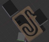
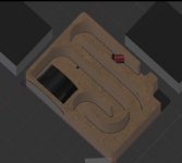
Just thought i'd post up some progress i'm having with a parametric design for small / micro Transmission Line speakers
I've knocked up a quick blog also at L̶a̶t̶e̶ ̶T̶h̶i̶r̶t̶i̶e̶s̶, Early Fourties, Tools, Electronics, Life – Been reading way too many maker blogs. Here's my contribution
The goal,
Make as small as possible a 3D printable Transmission Line enclosure for those speakers......and, as a 'side' project, make the enclosure totally parametric!
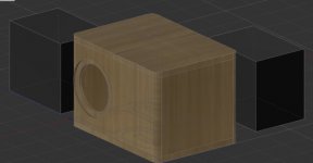
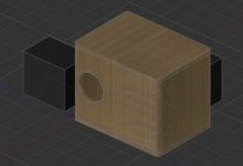
I've attached some pictures showing the different shapes the enclosure takes when you specify different parameters. The first photo is my chosen size of speaker....The enclosure is on its side in the pictures.
The black boxes are there for scale, they're the size of my existing bundled HT speakers that i'm replacing
The parameters
Speaker enclosure Width - this sets the Width of the waveguide -
since the total speaker width is Wall thickness + waveguide width + wall thickness
SD - This sets the 'Height' of the waveguide....
we already know the total surface area needed, we know the speaker width so it's easy to find the waveguide height
Both the above set the size of the rectangular 'output' of the waveguide and therfore the entire waveguide size
Wall Thickness - just as it says, you can go from 1mm to whatever really depending on how sturdy you want the thing
Tolerance - currently 0.5mm - gives a bit of wiggle room each side for attaching the pieces together, i.e. the 'side' plate sits within th e middle part by a few mm...this part is shrunk by 0.5mm each side to allow the centre part to locate and lock on nicely. I'm intending to glue the lot together
Waveguide Correction - once you get the right looking size / shape of speaker, you'll need to 'tune' the length of the waveguide - this number basically moves the port up and down at the rear - when the port's at the top, the guide is about 70cm long, when it's at the bottom, it's about 82cm long...allowing a good tuning range of frequencies.
I'm working on changing this a little to add an extra waveguide 'fold' in
can't see any reason why I can't get a 12" sub into it along with a 2 meter waveguide....will be interesting printing it
you can also set the speaker sizes
It's a 3 piece print - Two sides and the centre wavy bit
I'm pretty much finished with the design now, just gotta measure accuratley the waveguide length
Question - where do you start measuring the waveguide length? - from the back of the speaker?
Attachments
Last edited:
What waveguide? Do you mean the line / pipe (they aren't generally used as synonyms outside Bo$e's marketing department 😉 )? If so, axial length is generally taken as from the sealed end (aka 'throat') along the centreline to the terminus. This is in effect a ducted vent ported box though, so it's more or less from where the driver chamber exhausts into the duct.
Where did you get the chamber size and the pipe CSA and length from? Why the smooth curves? Note that smooth curves only have any significant acoustical impact in reducing losses of the [unwanted] higher frequencies; the LF wavelengths are too long to be affected. Pipe tuning is a function of axial length and taper (which creates acoustical length). The amount of gain you'll get (to a point) is a function of bulk, viz. pipe cross section. End-loading, i.e. placing the driver at or in extreme proximity to the throat provides maximum excitation of the fundamental and all relevant (odd) harmonics.
Where did you get the chamber size and the pipe CSA and length from? Why the smooth curves? Note that smooth curves only have any significant acoustical impact in reducing losses of the [unwanted] higher frequencies; the LF wavelengths are too long to be affected. Pipe tuning is a function of axial length and taper (which creates acoustical length). The amount of gain you'll get (to a point) is a function of bulk, viz. pipe cross section. End-loading, i.e. placing the driver at or in extreme proximity to the throat provides maximum excitation of the fundamental and all relevant (odd) harmonics.
I'm learning the terminology here!
Thanks for answering the question though
Chamber size- Figured I'd 'play' and see what works. The VAS is 0.94L so figured I'd need a cube of at least 9.8cm x 9.8cm x 9.8cm or so, I've used a slightly bigger volume here.
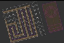
RE the smooth curves - It just looked better when designing, no real 'need' to do them other than having fun designing it and looking 'cool' as it's not so common to see. But, good to know, my early iterations were entirely square based - See pic - The right hand bit just has all the relevant 'pieces' scaled to make sure it all fits properly, it's the front and rear of the speaker 'merged'
scale wise - each 'large' square is about 3.5cm and each small square is 1cm here - assuming the speaker width is >100cm (it has to be) then chamber volume is always >1L!
Pipe CSA is directly related to SD - The Speaker CSA, it's either same as, or slightly more than. Basically I convert the Speaker CSA from circular to rectangular. that's easy enough as manually setting one dimension (the longest) of the pipe, we can calculate the other (Shortest)
There's no taper (yet) as i'm still trying to understand the rules of thumb needed for port CSA < Speaker SD and general SD >> Port CSA > SD
Overall, i'm not chasing Huge Bass from this , i have a small sub that handles the deep stuff, I'm just trying to optimise what I can get from as small as enclosure as I can, whilst learning Fusion 360 and 'having fun'
any pointers are welcomed 🙂 I'm new to all this
Attachments
Oh, Length - it's 1/4 wavelength - The speaker has an FS of 119.8Hz which gives a wavelength of 287cm (at room temperature) - which comes to about 72cm....
In theory that means I can tune from about 122Hz (70cm) to 104Hz (82cm)....
I've not delved into mass loading or stuffing yet....Figured I'd get the basics sorted first, ask for critiques then tweak away!
In theory that means I can tune from about 122Hz (70cm) to 104Hz (82cm)....
I've not delved into mass loading or stuffing yet....Figured I'd get the basics sorted first, ask for critiques then tweak away!
Well, if you want critique, smooth curves are a bad idea, and line CSA has no direct functional relationship to driver Sd so don't go too far down that route; it usually ends up causing insufficient internal volume and limited gain (output) as a result. Not saying that's the case here; I haven't had chance to do any rough calculations, but it's worth keeping in mind.
Thanks for the feedback, I’ll read up a lot more on things now!
And I may just have to go back to square stuff as calculating line volume on the curved one’s gonna be a Right pain 😛
And I may just have to go back to square stuff as calculating line volume on the curved one’s gonna be a Right pain 😛
You might play around with foam core first to get a feel of how the TL will sound before committing to wood. It would be easy enough to gin up something like this in an hour with foam core and hot melt glue for $2. No harm done. I built something like this as one of my first BLH's with a TC9FD - without any modeling or simulation. It sounded a bit unbalanced - but I now realize probably what I needed was baffle step correction.
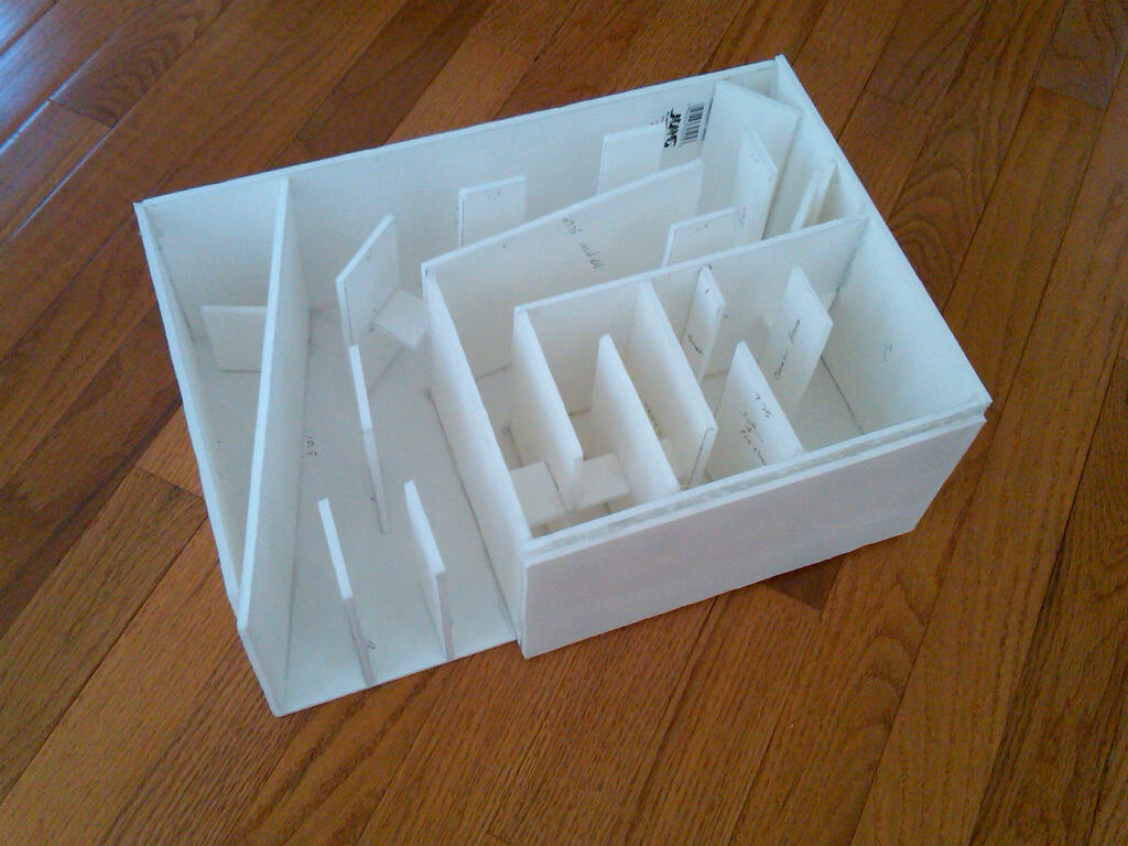
Look at this thread's Index to get some ideas:
Foam Core Board Speaker Enclosures?
This one followed Scottmoose's design:
https://www.diyaudio.com/forums/ful...board-speaker-enclosures-255.html#post4159850
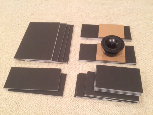
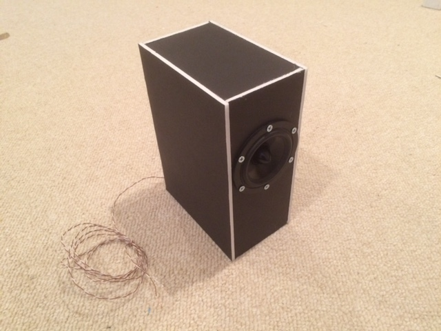
Look at this thread's Index to get some ideas:
Foam Core Board Speaker Enclosures?
This one followed Scottmoose's design:
https://www.diyaudio.com/forums/ful...board-speaker-enclosures-255.html#post4159850


After the guidance here I’ve now realised that a TL is kind of like a resonance chamber with a hole at the end!
Looks like it’s the volume of air within the chamber that sets the sound level and the length of the chamber that sets the resonance frequency,
The tampering of the chamber Area to < SD helps shorten the chamber length
So, When I redesign
Square corners
Tapered TL (preferable but not critical? - from 1 unit to 0.5 units?)
I can’t quite figure out though,
How do I work with TL volume?
- let’s say the ideal calculated volume of a ported cab is about 6L
Does the TL volume need to be 6L?
If I make it (say) 3 L would that just shift down in sound level the resonant frequency?
Get acquainted with some of the TL software out there.
There's HornResp and LATL, the latter not being supported anymore but still works fine.
That will take the guess work out of the equation, and you'll directly see the relationships between all those variables.
There's HornResp and LATL, the latter not being supported anymore but still works fine.
That will take the guess work out of the equation, and you'll directly see the relationships between all those variables.
A rule-of-thumb for a basic 1/4 WL TL net volume [Vb] is 4-10x Vas, i.e. the range for an infinite baffle alignment.
If you want high accuracy, then use this design routine: http://www.quarter-wave.com/TLs/Alignment_Tables.pdf
If you don't want to work it out 'long hand', then use this Excel worksheet: http://www.quarter-wave.com/TLs/Alignment_Tables_Calculator_3_3_09.xls
GM
If you want high accuracy, then use this design routine: http://www.quarter-wave.com/TLs/Alignment_Tables.pdf
If you don't want to work it out 'long hand', then use this Excel worksheet: http://www.quarter-wave.com/TLs/Alignment_Tables_Calculator_3_3_09.xls
GM
Last edited:
All that said, what you apparently have is a reflex with a very long vent, but not sure what its tuning is, though normally not a good plan to tune < a 1/2 octave below [0.707x Fs] unless with true horn loading.
WRT keeping size as small as practical, an EBS alignment [extended bass shelf] was once popular for high Qt drivers, so with a 1.3 L box with a vent area [Av] = [Sd], the minimum size for a TL terminus; Hornresp 'says' it's 54 cm long for an 86.7 Hz tuning [Fb] = ~2.9 L net.
GM
WRT keeping size as small as practical, an EBS alignment [extended bass shelf] was once popular for high Qt drivers, so with a 1.3 L box with a vent area [Av] = [Sd], the minimum size for a TL terminus; Hornresp 'says' it's 54 cm long for an 86.7 Hz tuning [Fb] = ~2.9 L net.
GM
Attachments
All that said, what you apparently have is a reflex with a very long vent, but not sure what its tuning is, though normally not a good plan to tune < a 1/2 octave below [0.707x Fs] unless with true horn loading.
WRT keeping size as small as practical, an EBS alignment [extended bass shelf] was once popular for high Qt drivers, so with a 1.3 L box with a vent area [Av] = [Sd], the minimum size for a TL terminus; Hornresp 'says' it's 54 cm long for an 86.7 Hz tuning [Fb] = ~2.9 L net.
GM
Wow, thanks for this response! and that text file, will have a play now to see what I can knock up!...Looks feasible to do a single print with some supports with such a small box!
- Home
- Loudspeakers
- Full Range
- Dayton PS95-8 Small TL enclosure progress

